
Logic
Complete guide on how to set up the Logic component within the Ilevia Manager configuration software.
Introduction
This component allows you to create boolean operations (AND / OR / XOR). The operation is evaluated when an input state changes. For each input, you can define whether to consider the change from ON to OFF or from OFF to ON. You can define up to 4 outputs, each of which acquires the value resulting from the operation.
Use cases
The user can use this component to calculate parameters coming from load control, where a logical operation can be applied to obtain a result.
Component properties
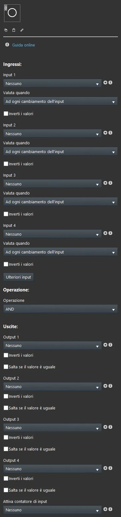
GUI
This component was created using the Graphic UI gateway.
You can refer to the chapter “Gateway / protocols” for further information.
Input:
Input: option list, Colored Info, Text Info, Switches, Lock, button;
Evaluate when:
– Input “n” changes from Off to On: the operation is executed only when the input changes to On;
– Input “n” changes from On to Off: the operation is executed only when the input changes to Off;
– On every change of Input “n”: the operation is executed when the input changes to either On or Off;
Invert value: checkbox that inverts the values 0=On, 1=Off;
Additional inputs:
The component parameters allow you to select up to 4 different inputs. To add more, click the “Additional inputs” button and drag the required inputs into the dialog window that opens.
Operations:
– AND: the operation is executed only when all inputs behave as defined;
– OR: the operation is executed when at least one input behaves as defined;
– XOR: the operation is executed only when a single input is active;
– SUM: this function sums all inputs present as Info components. It can be used, for example, to sum two values coming from two energy meters;
– AVERAGE: this function calculates the average of all inputs present as Info components. It can be used, for example, in a system with multiple rooms to determine the average temperature;
– MAX: This function calculates the maximum of the inputs present as Info components;
– MIN: This function calculates the minimum of all inputs present as Info components.
Output:
Output: Option menu, Colored Info, Text Info, Switches, secure switch, button;
Invert value: A checkbox that allows you to invert the output value from 0=On, 1=Off.
Active input counter: Info component that shows the number of inputs On;
HELP
The Logic configuration can be done simply by using the component drag and drop function. By setting the component parameters, you can use the Option List, or add them from the “Components” section to the component selection field.
Reminder before continuing:
Download and install the Logic module to enable plugins (link);
After uploading the Ilevia project to the server, wait a couple of minutes for the logic to start.
Example project: logic with more than 4 inputs
Step 1:
Add a new Logic component and 11 Switch components within the project.
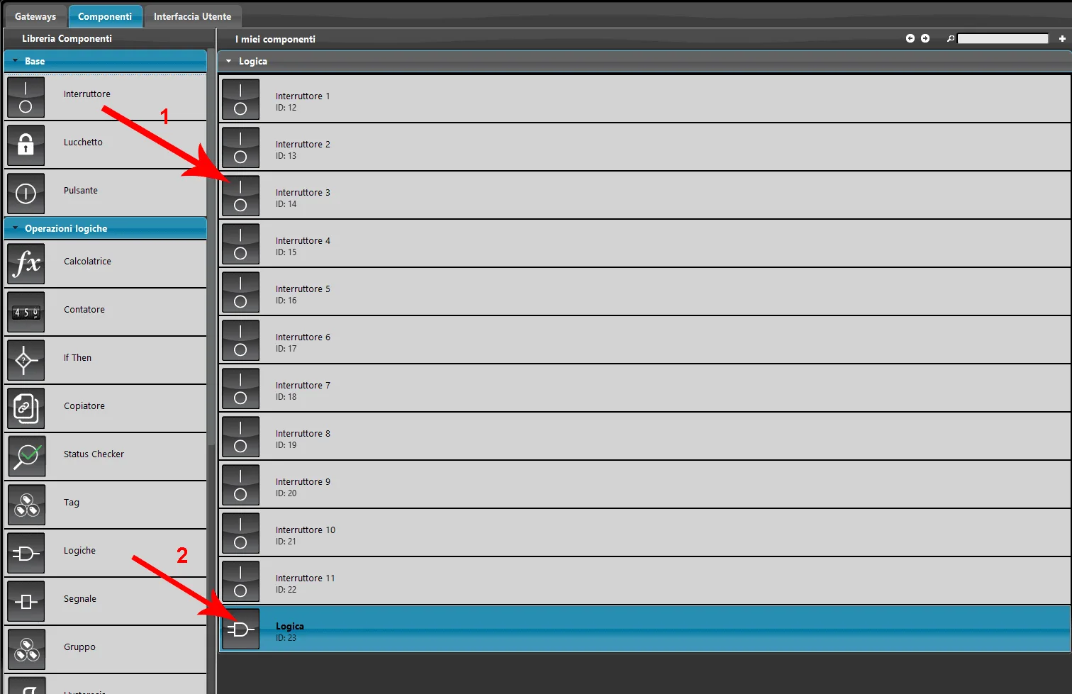
Step 2:
Click the “Additional inputs” button: a new window will appear in Ilevia Manager. Add 10 Switch components to the list by dragging them or by double-clicking the component with the left mouse button.
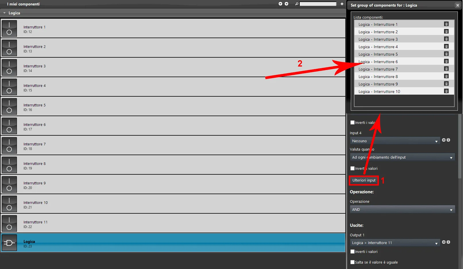
Step 3:
Select an operation type. In this example, we will use the “OR” operation.
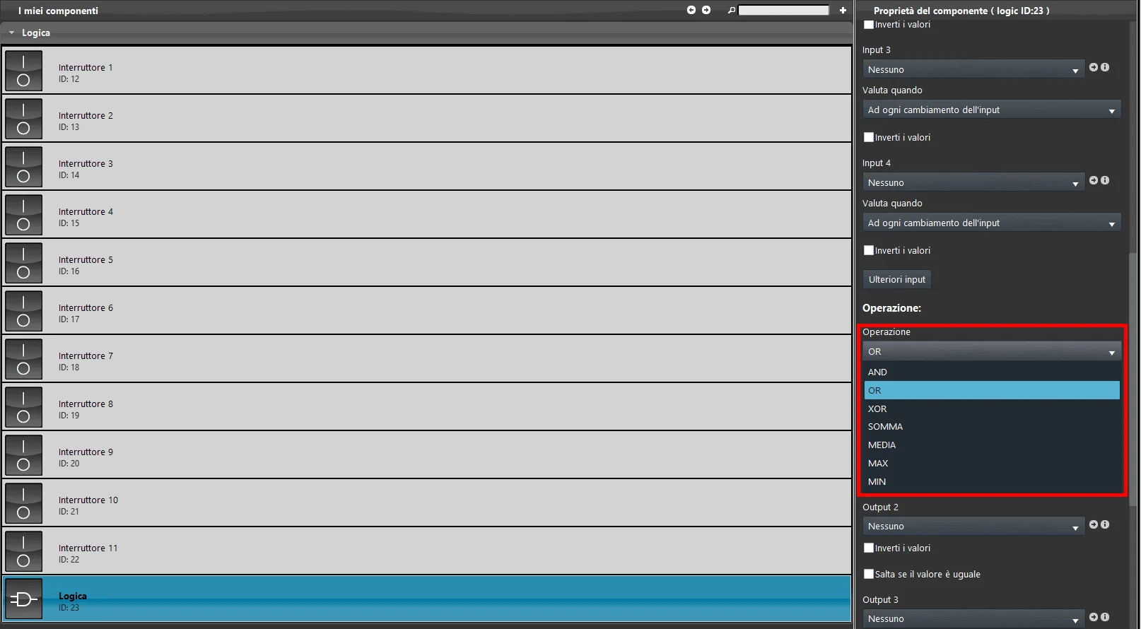
Step 4:
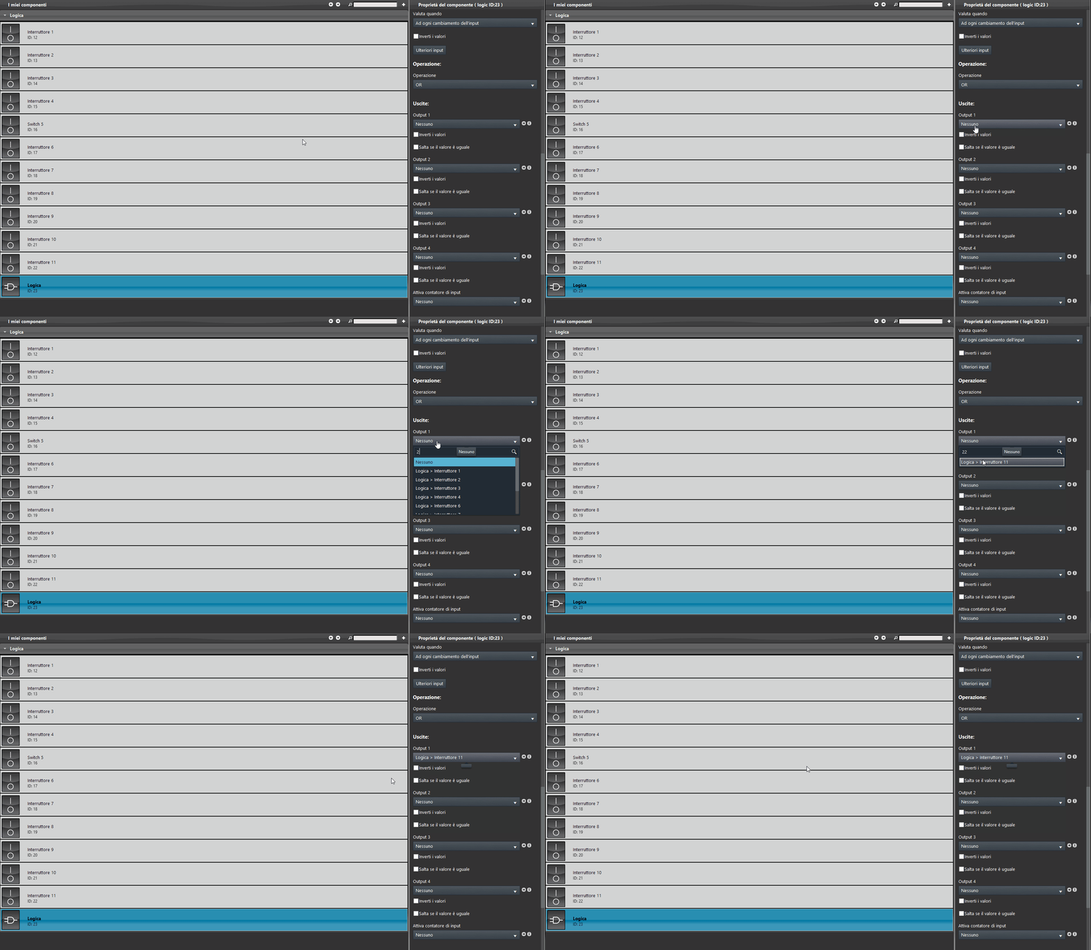
Add the output components. In the first output parameter, select the last available Switch component.
Step 5:
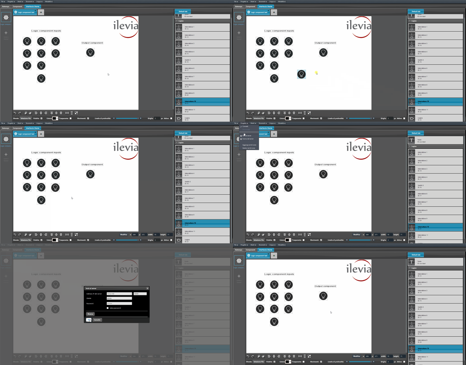
Finally, add all the components within the user interface and upload the project to the server.
Visual result of the logical operation
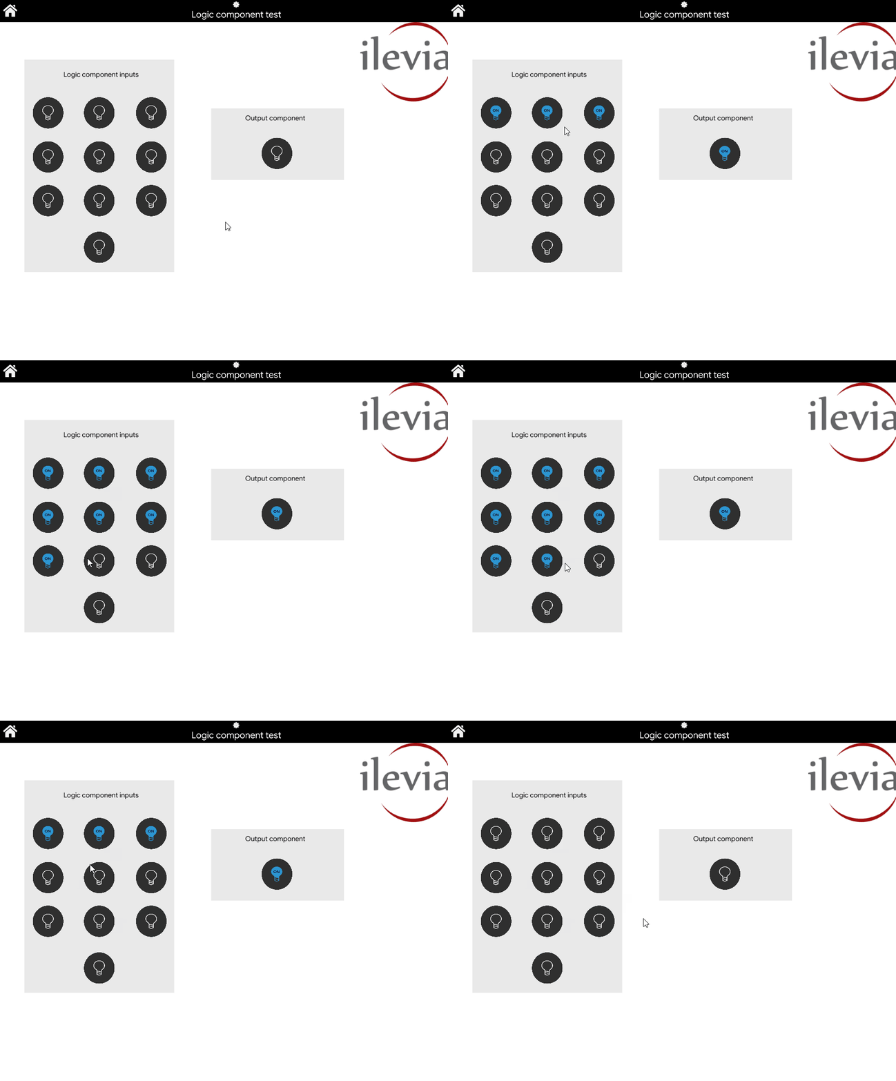
Below is the representation of the Logic component configured in the previous steps. As you can see, when one of the input components changes state, the output component changes state as well.
Click the link below to download the demo project and try it.