
Modbus RTU/ASCII and Modbus TCP Gateway: parameters
Configure Modbus RTU/ASCII and Modbus TCP on X1 Plus: ports, timeout, zero-based registers, reading and writing, value conversion and Manager images.
This guide explains how to connect X1 Plus to Modbus devices and configure the components in Manager. First set up the gateway, then specify the device, function and registers to use for each component.
Keep the manufacturer’s Modbus map at hand: it must show communication parameters, Unit ID, supported functions, addresses, format and scale of the values. The English names shown here correspond to the Manager fields.
Which gateway to choose
Connecting X1 Plus | Protocol in Manager |
|---|---|
RS485 serial devices | Modbus RTU/ASCII. For ASCII, also enable Ascii transform. |
Modbus device or interface on the IP network | Modbus TCP. Set the device or interface IP address and its port. |
In Gateways, create or select the gateway, assign a recognizable Name, and leave Enabled active to use it. For the procedure, see Add and remove a gateway.
Modbus RTU/ASCII
Gateway properties
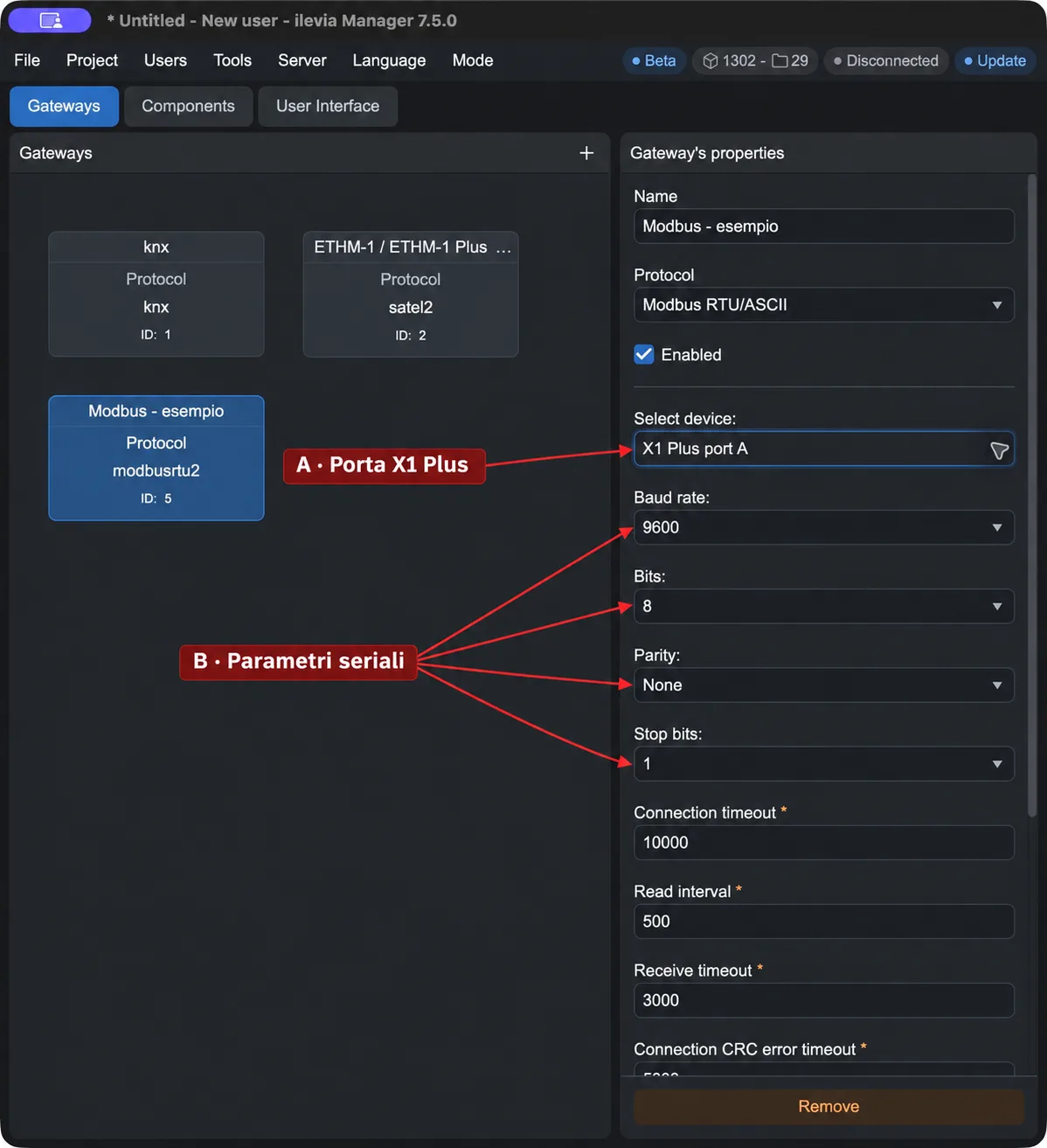
A · Connection port. In Select device, choose X1 Plus port A or X1 Plus port B according to the RS485 port used. Refer to the server instructions and the relevant hardware documentation to identify terminals and port.
B · Serial parameters. Baud rate, Bits, Parity and Stop bits must match the device settings. The values shown in the screen are an example, not a configuration valid for all devices.
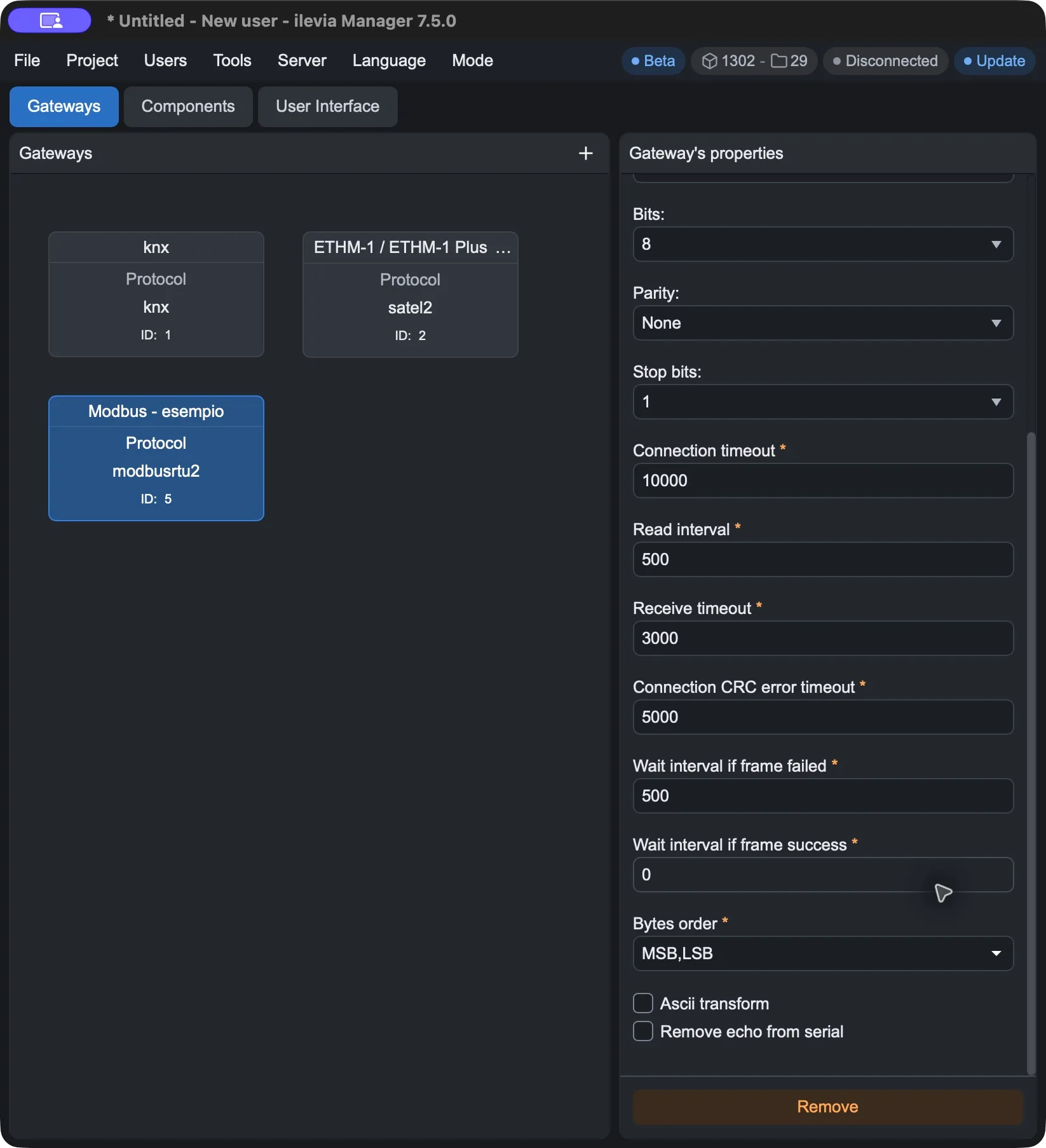
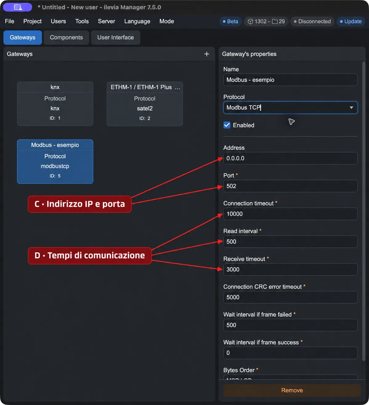
Gateway screens: on the left, the X1 Plus RS485 example; in the center, timing and serial options; on the right, Modbus TCP. Click the images to enlarge them.
Field | How to set it |
|---|---|
Baud rate | Serial line speed. It must match the value set on the devices. |
Bits / Parity / Stop bits | Number of data bits, parity and stop bits: enter the values required by the manufacturer. |
Ascii transform | Enables Modbus ASCII communication. Leave it disabled for Modbus RTU. |
Remove echo from serial | Allows the serial transmission echo to be removed. If the hardware already removes the echo automatically, leave this option disabled. |
Modbus TCP
Gateway properties
C · IP address and port. With Protocol = Modbus TCP, Address is the IP address of the Modbus device or interface reachable from X1 Plus. The initial value 0.0.0.0 must be replaced. Port is the device listening port; in Manager the default value is 502.
The IP address in Address identifies the device or interface on the network. Unit ID, configured in the component, identifies the target Modbus unit: the two fields are not interchangeable.
Communication timing and byte order
D · Communication timing. The timing fields are expressed in milliseconds: 1000 ms equals 1 second. Use the values required by the device; the values in the table are the initial values observed in Manager.
Field | Meaning | Initial value |
|---|---|---|
Connection timeout | Maximum time to open the connection. | 10000 ms |
Read interval | Interval between reads. | 500 ms |
Receive timeout | Maximum time to wait for the device response. | 3000 ms |
Connection CRC error timeout | Waiting time before retrying after a communication/CRC error. | 5000 ms |
Wait interval if frame failed | Waiting time after an unsuccessful exchange. | 500 ms |
Wait interval if frame success | Waiting time after a successful exchange. | 0 ms |
Bytes order / Bytes Order. Defines the byte order to interpret in Modbus data. Set it according to the manufacturer’s map. This field is also present in Modbus TCP: it does not apply only to the serial line. For values across multiple registers, also check the order indicated in the component Type.
Configuring a Modbus component
Open Components and select the component: for example Info for a measurement or Switch for a command.
In the Gateway field, associate the Modbus gateway configured for X1 Plus.
Scroll to the MODBUS section. Configure Read for reading and, in components that support it, Write for writing.
Fill in Data Transform according to the format and scale indicated by the manufacturer.
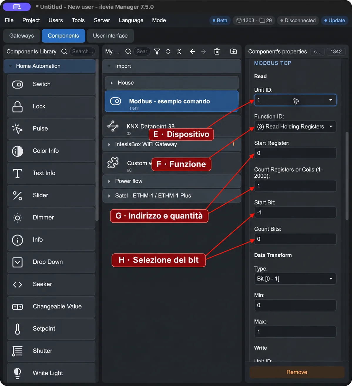
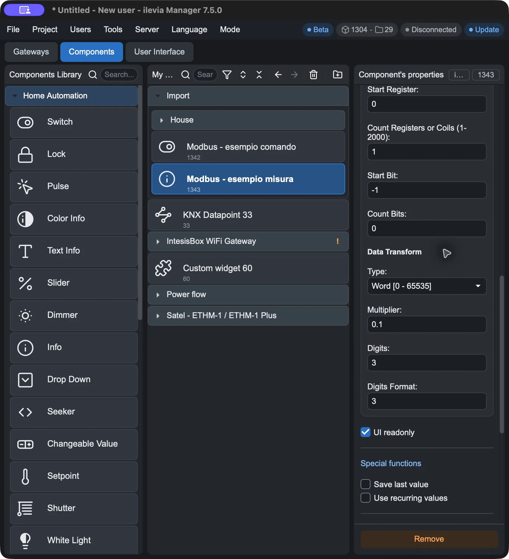
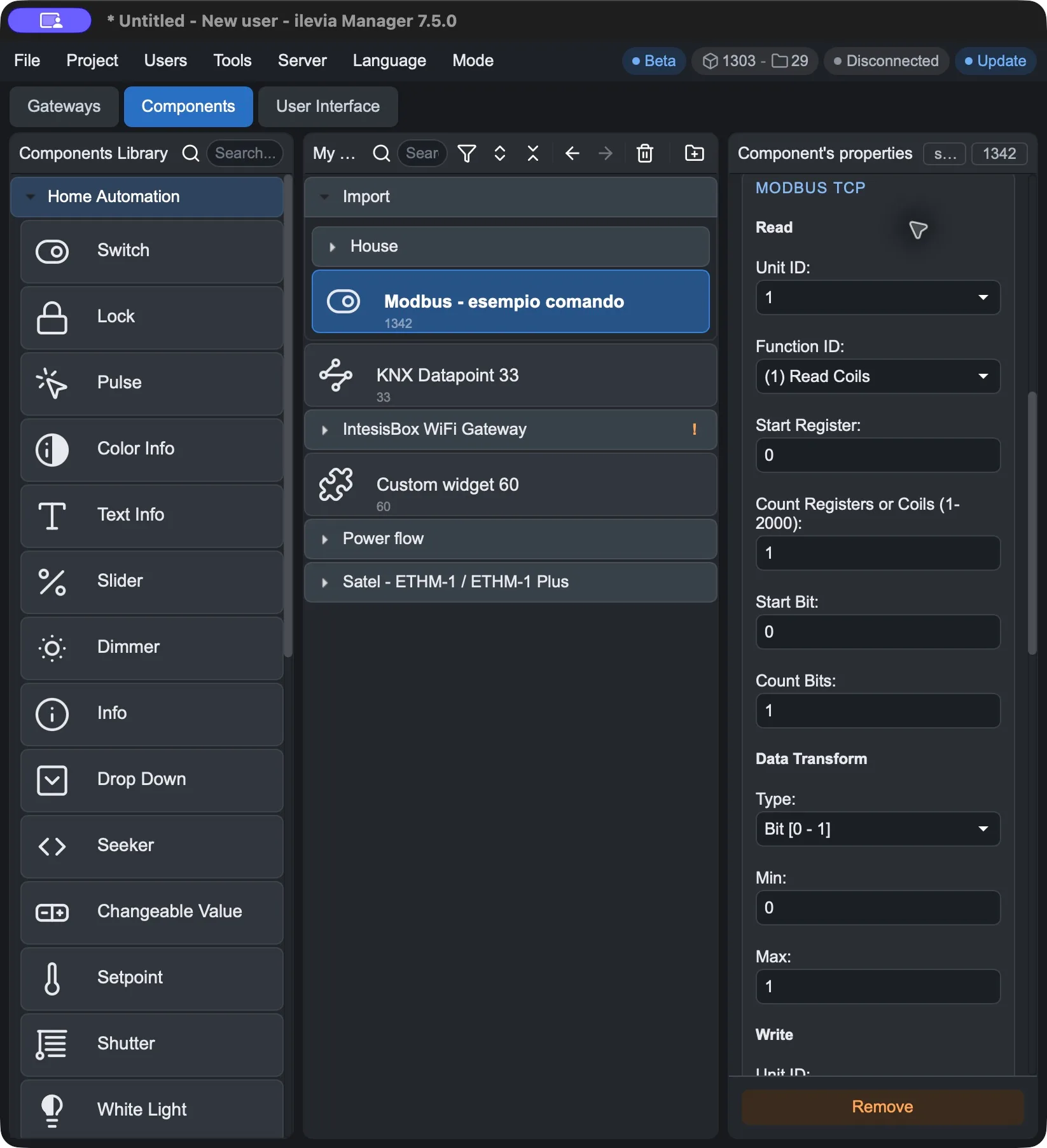
The following screens show the Read fields, an example of Data Transform in the Info component, and a coil read. These are separate examples: do not copy the values without comparing them with the device map.
Read / Write field | Meaning |
|---|---|
E · Unit ID | Modbus unit identifier. It must match the value set on the device. In the read example it is 1. |
F · Function ID | Operation to perform: choose the function specified by the device map and by the data type. Reading and writing may require different functions. |
G · Start Register | Starting address with base 0. If the manual indicates the first holding register as 40001, in Manager set Start Register = 0 and the holding register read function. If the manual already shows an offset with base 0, use that offset. |
G · Count Registers or Coils | Number of registers or coils involved, starting from the initial address. It must be consistent with the function, data format and device limits. |
H · Start Bit / Count Bits | They allow selecting a portion of bits. Start Bit = -1 and Count Bits = 0 indicate that the entire word is taken. To extract single bits, use the position and quantity specified in the device map. |
Read and Write must be configured separately. Read acquires the value or status; Write sends the command. Do not assume they use the same address or the same function: verify both in the manufacturer’s documentation.
Transforming the value: Data Transform
Field | Meaning |
|---|---|
Type | Format used to interpret the data: for example Bit for a binary value, Word for a 16-bit unsigned integer, Int16 for a signed integer. For multi-register data, also choose the correct order, as indicated by the manufacturer. |
Min / Max, when present | Configurable value limits for the component type. Set them consistently with the data and the function used. |
Multiplier | Factor by which the read value is multiplied. If the device sends 253 to mean 25.3, use 0.1: 253 × 0,1 = 25,3. |
Digits | Rounding applied to the read value. |
Digits Format | Number of decimal places displayed in the app. This is separate from the value rounding configured in Digits. |
In the Info screen, the example uses Type = Word and Multiplier = 0.1. Choosing the format and choosing the scale are two separate steps: a correct multiplier does not fix an incorrect format or byte order.
Example: reading a coil
A coil represents a binary value. In the screen, the example uses Unit ID = 1, Function ID = (1) Read Coils, Start Register = 0 and Count Registers or Coils = 1. The bit selection fields are Start Bit = 0 and Count Bits = 1, with Type = Bit.
Start Register identifies which coil the read starts from; Start Bit selects the bit in the received data. These are two different parameters. To read a different coil, use the base-0 address indicated in the device map.
Example connections with X1 Plus
X1 Plus and RS485 devices
Connection: X1 Plus → RS485 port A or B → Modbus RTU/ASCII devices. Select the same port in the gateway and set consistent serial parameters on all devices on the line.
For wiring, use the X1 Plus hardware diagram and the one for the connected devices. Check the RS485 signal matching and the manufacturer’s instructions on common reference, shielding and termination; A/B labels may vary between manufacturers.
X1 Plus and Modbus TCP devices
Connection: X1 Plus → Ethernet/IP network → Modbus TCP device or interface. X1 Plus must be able to reach the IP address and port configured in the gateway.
Apply the changes and check the result
Save the project with File → Save.
Upload the project to X1 Plus with Project → Upload to apply the changes. Repeat the upload whenever you want to apply new changes to the server.
Check a reading by comparing it with the value shown by the device. For command components, also verify the write and the subsequent status update.
Problem | Checks to perform |
|---|---|
No response | Enabled, RS485 port and serial parameters or IP address and TCP port; then Unit ID and connections. |
Error response from the device | Supported Function ID, base-0 address, requested quantity, and read/write permissions in the map. |
Inconsistent value | Type, number of registers, byte/register order, Start Bit / Count Bits, and Multiplier. |
Correct value but unexpected decimal places in the app | Digits and Digits Format. |
Downloadable example projects
The following projects contain examples of some device functions. Before using them with X1 Plus, check the gateway, port, Unit ID, communication parameters, and correspondence with your device map.
Download the project: SENECA S534-80 — three-phase energy meter
Download the project: Finder 7M24–7M38 — energy meter
Download the project: Dingtian — relay board
Download the project: Carlo Gavazzi EM340 — energy meter
Download the project: Fronius GEN24 — inverter
Download the project: IME CE2DF3DTCL1 — energy meter
Download the project: ASTRALPOOL Lumiplus — RGB light control