First steps with ILEVIA Manager
Create your first KNX command in ILEVIA Manager, set up the interface, and distinguish local save from upload to the server.
ILEVIA Manager is the desktop program used to prepare and manage the project for an ILEVIA system. It lets you organize connections, define components, and build the user interface. ILEVIA Control is the app used by the user to view and control the functions configured for the system.
This manual introduces the workflow and illustrates it with a small example: two groups, some KNX components, and a user page. Advanced protocol settings and server maintenance are outside the scope of this guide.
Choose the path
For the first exercise: set up groups and gateways, create the Switch, add it to the user interface, then save and transfer the project.
To add more controls: follow the optional exercises on Slider, Info, and Dimmer.
If you are starting from an ETS project: use the guided import as an alternative to manually creating components.
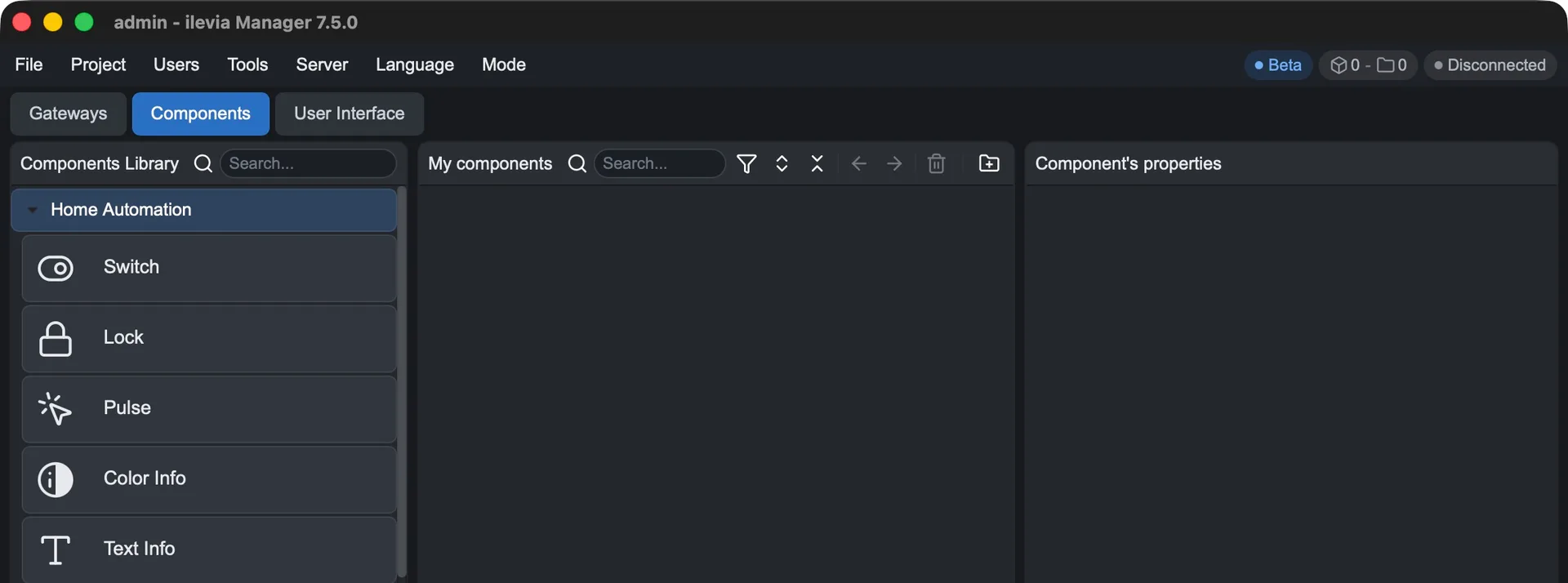
The Components section with the library on the left, project components in the center, and properties on the right.
Identify the main areas
Area | What it is used for |
|---|---|
Gateways | Organize the connections and protocols used by the project. |
Components | Work on the components that represent commands, states, and functions. |
User Interface | Organize the content and commands of the user interface. |
Read the project status
At the top right you can see the connection status. Disconnected means that Manager is not connected to a server. This status must be distinguished from having a project open on the PC.
The screenshots refer to ILEVIA Manager 7.5.0 on macOS, with menus in English. The names shown in the program are reported in the text. The Language menu also includes Italian to use the interface in Italian.
Create groups and prepare the KNX gateway
Open the project
Use File → Open… to open a project or File → New to start a new one. For an existing project, first keep a copy with File → Save As.
Create the group structure
Open Components. In the My components panel, click Add group, the button with the folder and + sign.
In the properties on the right, change Name to Ground floor.
Select Ground floor and click Add group again: the new group is created inside it.
Rename the subgroup Living room and select it before adding the components. Use the group arrows to expand and collapse its contents.
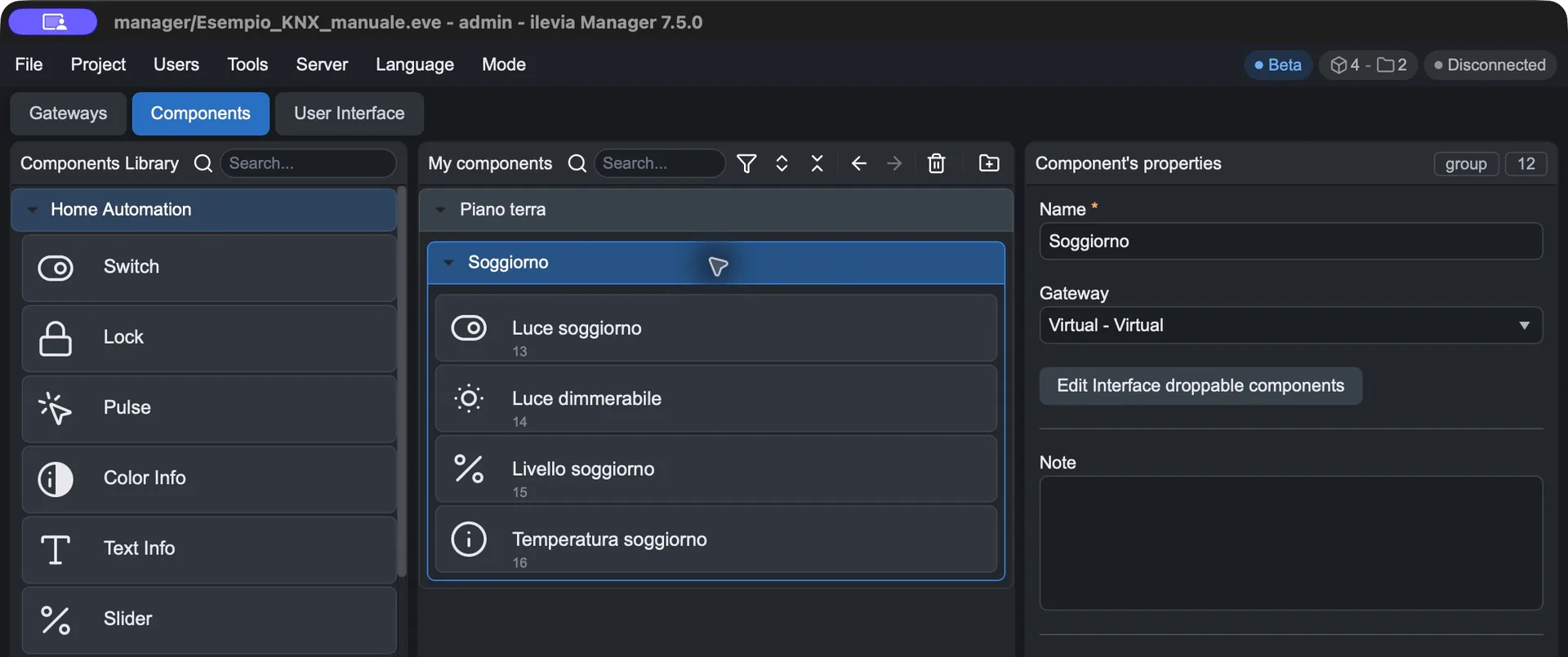
Example of the structure Ground floor → Living room with the room components.
At the end you must see Ground floor → Living room in My components. Groups organize the project components: the pages and menus visible to the user are built separately in User Interface.
Set up the KNX gateway
Open Gateways and click Add gateway (+).
Assign a name, for example KNX, and make sure Protocol is Knx.
Select the connection device used by the system and fill in the address and port according to its configuration. Then return to Components.
At the end, the KNX gateway must be available for the components. In the following examples, assign KNX - Knx to each component that communicates on the bus. The group can remain a Virtual - Virtual container.
Create the first KNX command
In Components, select Living room, open Components Library → Home Automation, and double-click the type to insert. The component appears in the group; its properties are on the right. The Search fields let you search the library and the project.
All addresses shown here are for demonstration only. In a real system, use the group addresses and data types defined in the ETS project.
Switch to turn a light on and off
Insert Switch, rename it Living room light, and select the KNX - Knx gateway.
In the KNX section, fill in Write address with 1/0/1 and Feedback address with 1/0/2. The three fields separated by / represent the three parts of the address.
Distinguish between the command sent on the bus and the status feedback. The feedback must match the status address configured in ETS; do not treat the two addresses as interchangeable.
Result of the first exercise: Living room light must have the KNX gateway and the command and status addresses. You can now move on to Create a simple user interface, or continue with the optional exercises.
Add more controls: optional exercises
Slider for a light level
Select Living room and insert Slider with a double-click. Rename it Living room level and choose the KNX gateway.
For the example, set Min 0, Max 100, and Suffix %. Use Write address 1/1/1 and Feedback address 1/1/2.
In the example, the KNX value uses Range 0 - 255, KNX lower value 0, and KNX higher value 255. The 0–100 scale defines the level shown in the interface, while 0–255 represents the value on the bus: the maximum displayed corresponds to the maximum of the KNX scale. Always verify this correspondence with respect to the data type expected in ETS.
Info to display the temperature
Insert Info in the group and rename it Living room temperature. Select the KNX gateway.
Choose Temperature Decimal °C in the interface Data type field. In the KNX section, choose 9.1 - DPT_Value_Temp and set Feedback address 1/2/1.
Check the °C unit and keep UI readonly for simple reading. The value formatting and the KNX data type are two separate settings.
Combine command and level in a Dimmer
To create a single lighting command, also add Dimmer and name it Dimmable light. Keep the gateway Graphic UI - Gui; in the Switch field choose Living room light and in the Slider field choose Living room level. The Dimmer combines the two components already configured: in this example no new KNX addresses are assigned to it.
Check the mandatory fields and any ! symbols next to the components before proceeding. Save the local project.
Import an ETS project
The guided import is an alternative, optional path: use it if you have an ETS project, instead of creating all components manually. The Ets project procedure requires a .knxproj file exported from ETS.
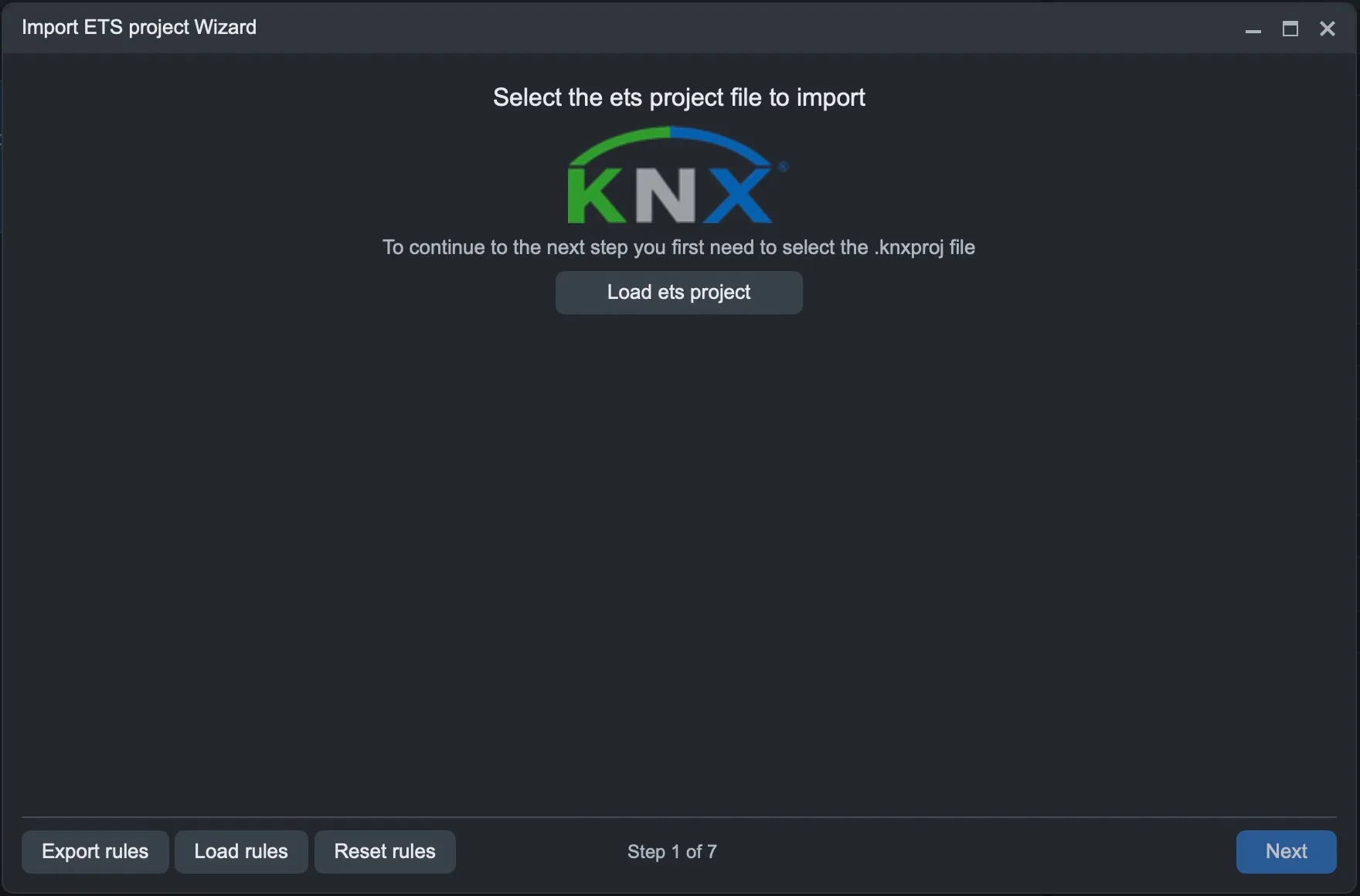
First screen of the Import ETS project Wizard: selecting the .knxproj file.
Start the procedure
Keep a copy of the Manager project you are working on.
Open Tools → Import → Ets project. Do not confuse this item with Ets groups.
In the Import ETS project Wizard window, click Load ets project and select the .knxproj file.
After loading, follow the steps proposed by the wizard with Next, checking the choices before finishing.
At the end, review the groups, components, gateway, and address and data type associations in Manager. Then prepare the desired interface.
For recognition rules and sample files, continue with Import from ETS.
Before using the imported components, check the associations proposed by the wizard and compare addresses and data types with the ETS project.
Create a simple user interface
The example uses a Classic user type. Check the User type field in Users → Edit user and select the appropriate user before working in User Interface. With a Map user, the editor layout is different from the one shown.
For the first exercise, create the Ground floor page and the Living room, then add Living room light. The screen also shows Dimmable light and Living room temperature: add them if you completed the optional exercises. The components remain organized in the project groups.
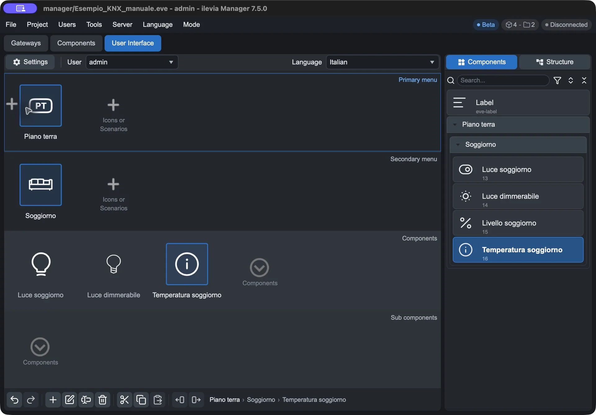
Interface with Ground floor icon, sofa for Living room, and three components.
Build menus and commands
Open User Interface and check User and Language to work on the correct user and language.
Select Primary menu and click Add (+). In the selector, choose Icons - Floors and the Ground floor icon, then confirm with Ok. Use Rename (F2) to name the item Ground floor and press Enter.
With Ground floor selected, select the Secondary menu area and click Add. Choose a sofa in Icons - Rooms, confirm, and rename the item Living room.
Select the Components area under the room. In the Components panel on the right, open Ground floor → Living room and double-click Living room light.
If you completed the optional exercises, select the Components area again and add Dimmable light and Living room temperature with a double-click.
Check the path and the order of the items; use Move left and Move right if necessary. Save the project.
Expected result: in the Living room, Living room light appears and, if you added them, also the Dimmer and the temperature. Do not add Living room level separately if you already use the Dimmer: it is recalled by that control. Device feedback is checked after connection and transfer to the server.
Choose icons that match the rooms
Icons help you recognize a room before even reading its name. Use a symbol that represents the room and keep a consistent style across the menus.
Change the icon of an already created item
In User Interface, select the menu item, for example Living room, and click Edit (Enter).
In the options window, double-click the image next to Icon to open Icon selector.
Open Icons - Rooms and select the appropriate symbol. For a floor, open Icons - Floors instead. Check the preview of the selected icon.
Confirm with Ok in the selector and then again with Ok in the menu options.
Check that the icon and name are recognizable in the editor and save with File → Save.
Simple matches
Menu item | Recommended icon |
|---|---|
Ground floor | GF in the Icons - Floors category, used in the example. |
Living room | Sofa in Icons - Rooms, used in the example. |
Kitchen | Kitchen or cooktop in Icons - Rooms. |
Bedroom | Bed in Icons - Rooms. |
Bathroom | Washbasin, shower, or bathtub in Icons - Rooms. |
Study | Desk in Icons - Rooms. |
Keep the room name next to the symbol. Room icons identify the areas; icons for individual components should recall the function, for example a light bulb for a light.
The example shown uses icons from the library without custom colors. If you add more rooms, choose symbols from the same collection to get a consistent interface.
Save and connect to the server
The project file on the PC and the configuration on the server are two different destinations. Save the local work and always check the transfer direction before acting on the server.
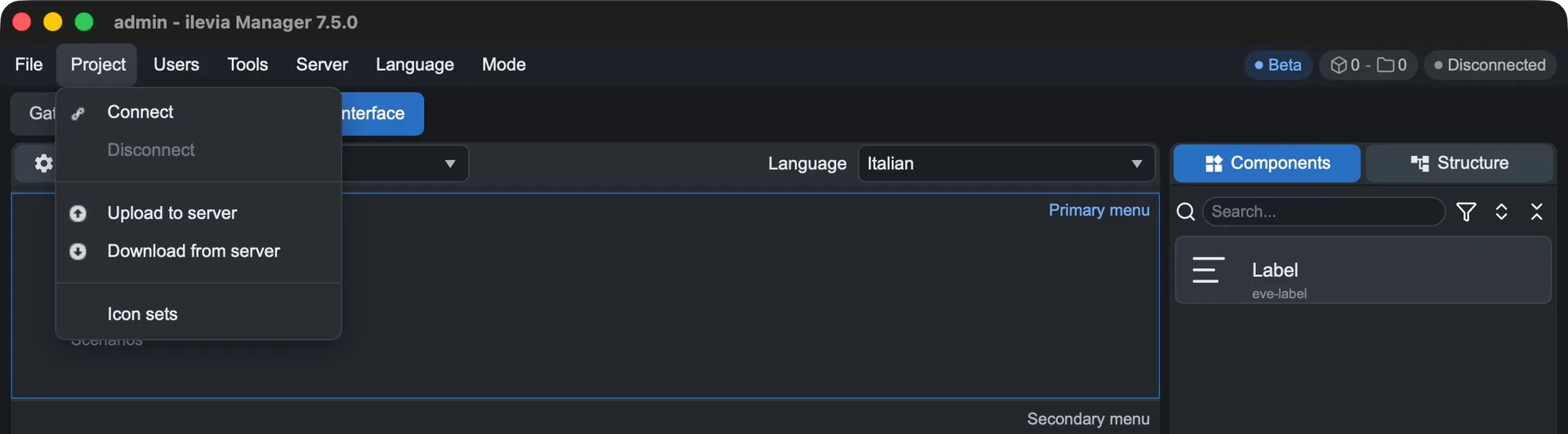
The Project menu groups the project connection and transfer commands.
Save the work on the PC
Use File → Save to save the local project. Use File → Save As to keep a copy with a different name or location. Local saving does not mean sending the configuration to the server.
Connect and choose the correct direction
Open Project → Connect.
Enter the server details and the credentials required for the system, then confirm the connection.
Check the connection status at the top of the window.
Choose the transfer command suitable for the task you need to perform, distinguishing between sending and downloading.
Command | Direction or effect |
|---|---|
Upload to server | Send the project from the PC to the server. |
Download from server | Download the project from the server to the PC. |
Disconnect | Disconnects from the server. |
Before downloading a project from the server, keep a copy of the local work. Before sending it, verify that you are connected to the correct server and that the configuration is ready to be used on the system.
Essential checks before closing
• The local project has been saved with a recognizable name.
• Gateway, components and interface refer to the correct system and user.
• Any transfer to the server has been completed and the result has been verified in the user interface.
If you need assistance, provide the Manager version, the operation performed, and the error message. For the Tools, Server and Mode menus, use the advanced guides.
Reference: application interface of ILEVIA Manager 7.5.0 installed on the PC, consulted on 8 November 2026. Command names and layout may vary between versions.