
KNX Gateway: properties and parameters
Configure the KNX connection and components in the Manager: addresses, port, NAT, virtual feedback and startup read, with annotated images and a command/status example.
The KNX gateway connects the Ilevia server to the system. First configure the connection to the bus, then associate the components with the gateway and set the ETS project group addresses.
The names in brackets correspond to the fields in the Manager in English.
Gateway properties
Open Gateways and select the KNX gateway. To create one, use the + button and choose Knx in the Protocol field.
Assign a recognizable name and leave Enabled active to use the gateway.
In Select device, choose the connection type actually used by the server, then fill in the fields described below.
For the create and remove commands, see Adding and removing a gateway.
Reference screens
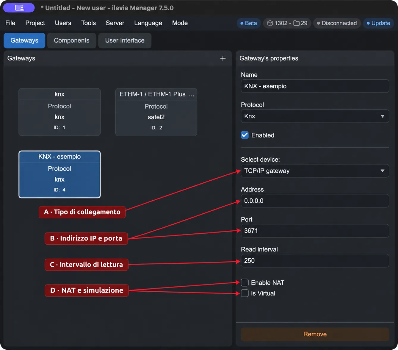
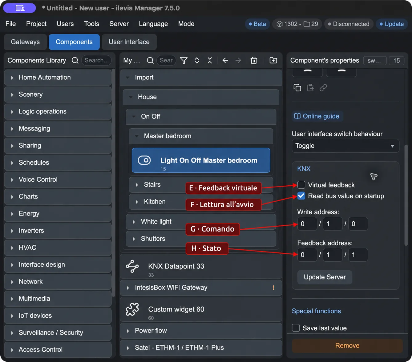
A–D: bus connection. E–H: component parameters. Click the images to enlarge them. The values shown are examples.
Selecting the connection and filling in the addresses
A · Connection type (Select device). The available options are X1, X1 Plus, Vivaldi iControl 4.0, TCP/IP gateway and USB/Serial. Select the one that matches the hardware and connection of the system.
Field | How to fill it in |
|---|---|
Name / Protocol / Enabled | Name identifies the gateway in the project. Protocol must be Knx. Enabled enables or disables the gateway. |
B · Address with TCP/IP gateway | Enter the IP address of the KNXnet/IP interface reachable by the Ilevia server. The initial value 0.0.0.0 must be replaced with the interface address. |
B · Port with TCP/IP gateway | Enter the port configured on the KNXnet/IP interface. The default value in the Manager is 3671. |
Address with local connection or USB/Serial | When the field requires a serial path, use the one of the device connected to the server. In the X1 example, the path is /dev/ttyS1: it is not an IP address. |
KNX Physical address, when present | This is the KNX individual address of the connection, in the area.line.device format, for example 15.15.250. It must be consistent with the system and not duplicate another device. |
C · Read interval | Interval between group address read requests, expressed in milliseconds. The default value in the Manager is 250 ms. |
Physical address and group address serve different purposes. An individual address such as 15.15.250 identifies a device on the bus; a group address such as 0/1/0 identifies a shared function, such as the command for a light.
NAT and virtual operation
D · Enable NAT. This applies to the KNXnet/IP connection through NAT. Enable it when the connection to the KNXnet/IP interface requires this mode. It is not used to enable X1 server discovery from ETS.
D · Is Virtual. Simulates the KNX connection without a physical bus connection. Use it for a virtual configuration; to communicate with the real KNX system, leave the option disabled.
KNX component parameters
Open Components and select the component to configure.
In the Gateway field, associate the correct KNX gateway.
Scroll through the properties to the KNX section and set the group addresses defined by the ETS project.
Field | Meaning |
|---|---|
G · Write address | Group address used to send the command from the component to the KNX bus. For a light, it is the on/off command address. |
H · Feedback address | Group address from which the component receives the value or status. For a light, it is normally the status address returned by the actuator. |
E · Virtual feedback | When the component receives a telegram on the Write address, it generates a telegram with the same value on the Feedback address. This is useful, for example, to connect KNX to other protocols. |
F · Read bus value on startup | When the project starts on the server, it sends a read request to the Feedback address to acquire the initial value from the bus. |
Startup reading can update the status only if the KNX device responds to the request on the configured address. Check the group object association and the related settings in the ETS project.
If the actuator has a status address, use that one in Feedback address. If the ETS project uses the same address for command and status, enter the same address in both fields, checking the device behavior. Virtual feedback should be enabled only when you need to generate the feedback telegram: it does not represent a confirmation of the actuator's physical state.
Example: command and status of a light
In the component screen, Write address is 0/1/0 and Feedback address is 0/1/1. The addresses in your system must match the ETS project.
The command sent by Ilevia uses 0/1/0.
The actuator status telegram on 0/1/1 updates the component.
With Read bus value on startup enabled, at startup the server requests the value on 0/1/1.
With Virtual feedback disabled, feedback remains assigned to the KNX device. If you enable it, a telegram received on 0/1/0 generates the same value on 0/1/1.
Applying the changes and checking the result
Save the project with File → Save.
Upload the project to the server with Project → Upload to apply the changes. Repeat the upload whenever you want to apply new changes to the server.
Verify that the command reaches the actuator and that the feedback value updates the component in the control interface.
If the command works but the status does not update, check Feedback address and the status telegram configured in ETS. If communication is completely missing, check Enabled, the connection type, the address, the port, and whether the interface is reachable from the server.
For the save and load procedure, see Getting started with Ilevia Manager.