Gates, selectors and flip-flops
The nodes in the Gates category of Flow: Selector, Binary Encoder, Numeric Encoder and Decoder for routing signals, T Flip-Flop, RS, D and D Latch for storing a state, with tables and examples.
The nodes in the Gates category do two things: they route a signal (choose where to take it from or where to send it) and store a state (remember an event even after it has ended).
Routing signals
Node | What it does | Selector |
|---|---|---|
Selector | Chooses which input to send to the output, between two. | On/off |
Binary Encoder | Chooses which output to send the input to, between two. | On/off |
Numeric Encoder | Chooses which output to send the input to, among many. | Number from 1 |
Decoder | Chooses which input to send to the output, among many. | Number from 0 |
Selector
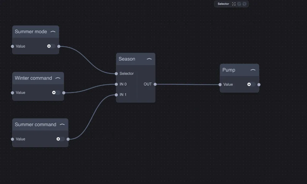
With Selector off, output OUT receives IN 0; with Selector on, it receives IN 1.
Example — summer/winter: the system pump receives the command from the winter thermostat or the summer thermostat according to Summer mode.
Binary Encoder
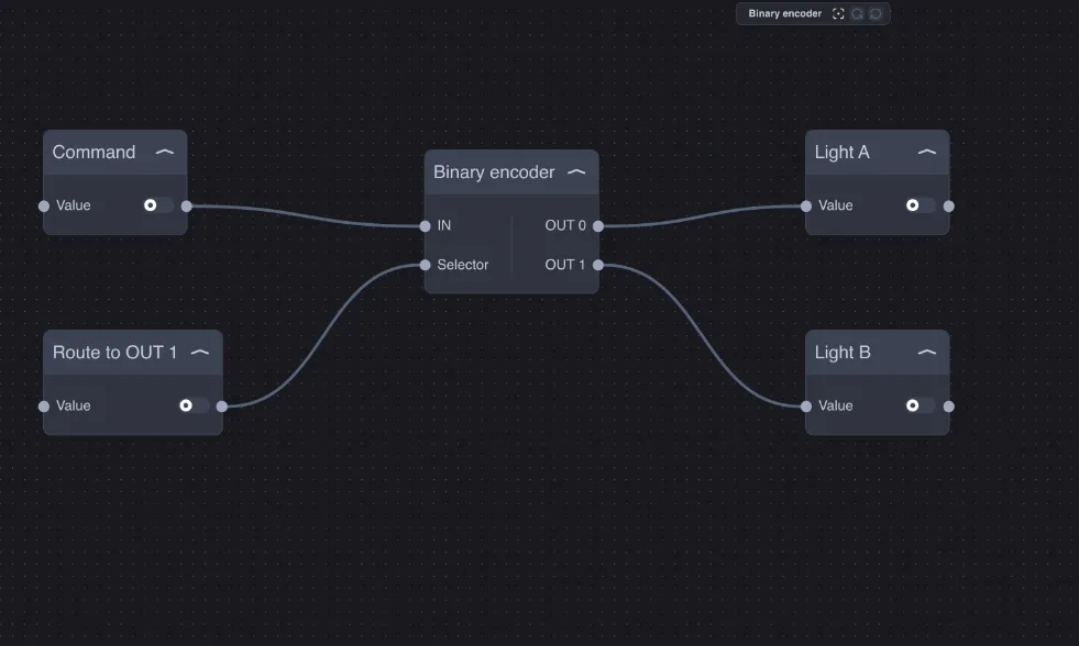
Sends the value of IN to OUT 0 (Selector off) or to OUT 1 (Selector on). The unselected output remains unchanged.
Example — one button, two lights: the same button controls light A or light B according to a Route to OUT 1 switch, for example day and night.
Numeric Encoder
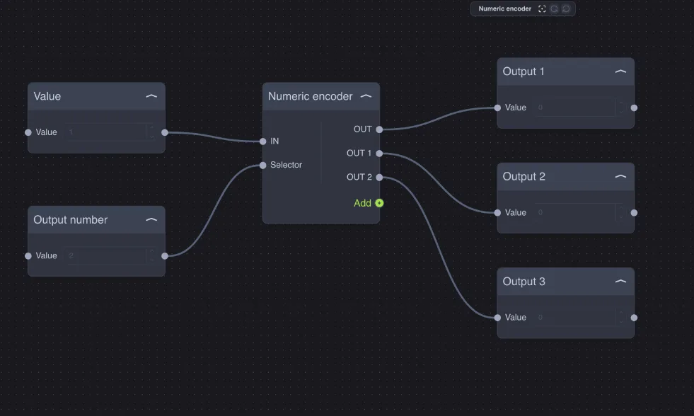
Sends the value of IN to the output selected by the Selector number: 1 = OUT, 2 = OUT 1, 3 = OUT 2… up to 10 outputs. The Add button adds outputs. The unselected outputs remain unchanged.
Example — one command for multiple zones: a Dropdown in the app selects the zone (1 = kitchen, 2 = living room, 3 = bedroom) and the "music on" button reaches only the selected zone.
Decoder
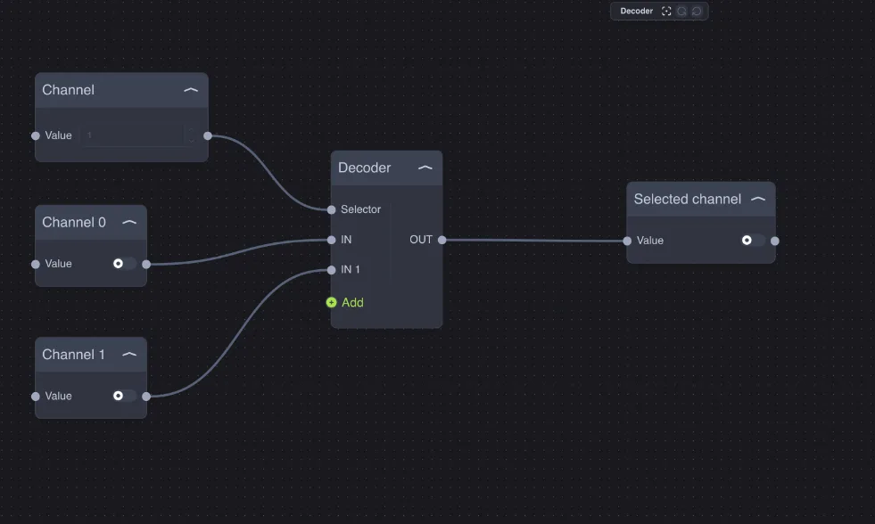
Sends the input selected by the Selector number to the OUT output: 0 = IN, 1 = IN 1, 2 = IN 2… up to 10 inputs. The Add button adds inputs.
Example — audio source: the channel selected in the app (0, 1, 2…) decides which source reaches the amplifier.
Watch the numbering: the Numeric Encoder counts from 1 (1 = first output), the Decoder counts from 0 (0 = first input). The selector must be an integer.
Storing a state
Flip-flops remember a state: their output depends not only on the current inputs, but also on what happened before. Rising edge means the moment when a signal changes from off to on.
T Flip-Flop (toggle)
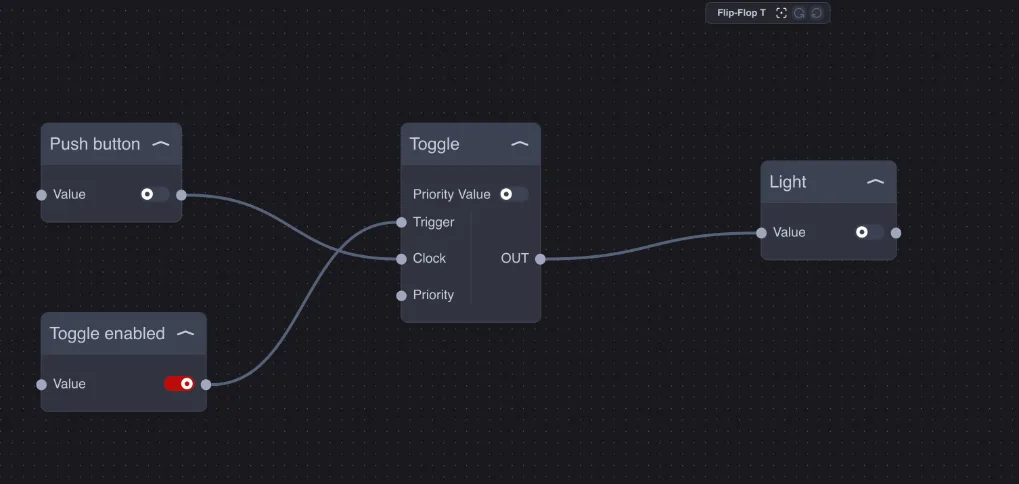
At each rising edge of Clock the OUT output toggles, but only if Trigger is on. If Priority is on, the output is forced to Priority Value, regardless of what arrives on Clock.
Example — step-by-step button: a pulse button turns the light on and off with each press. Toggle enabled on Trigger enables or blocks the button (for example at night); Priority forces the light off when you leave home.
RS Flip-Flop (set/reset)
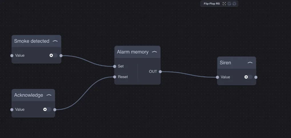
With Set on, the output turns on; with Reset on, it turns off; the output remains in the state it reached when both return off. If Set and Reset are on together, Set wins.
Example — alarm memory: the smoke detector turns the siren on; the siren stays on even when the smoke is gone, until someone presses Acknowledge. Since Set wins, as long as smoke is still present the siren cannot be silenced.
D Flip-Flop (data)
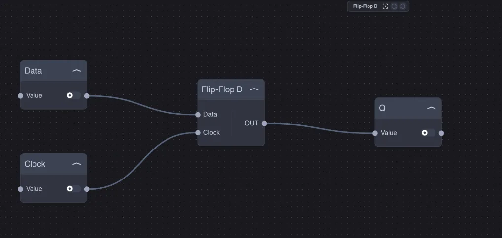
At the rising edge of Clock the output copies the value of Data and holds it until the next edge.
Example — snapshot of a state: at midnight (Clock) it records whether the boiler was on (Data), for a check the next morning.
D Latch
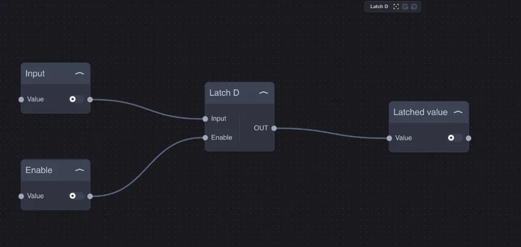
As long as Enable is on, the output follows Input; when Enable turns off, the output stays fixed at the last value.
Example — command hold: during cleaning (Enable off) the shutter value remains fixed even if commands arrive from the light sensor.