Timers and counters
The nodes in the Timers and counters categories of the Flow: Timer, Stairs Light, Trigger, Numeric Trigger, Astronomy Clock, Date/Hour, Repeat Command, Oscillator, Clock, and Counter, with properties, units of measure, and examples.
The nodes on this page bring time into logic: delays, automatic shutoff, pulses, schedules, sunrise and sunset, counts.
Node | Summary |
|---|---|
Delays switching on and off. | |
Timed light: turns off automatically after a set time. | |
Turns a change into a pulse. | |
Pulse when a number reaches a value. | |
Day or night according to sunrise and sunset. | |
Date, time, and day of the week. | |
Repeats a pulse several times. | |
Oscillator and Clock | Continuous pulses or blinking. |
Counts events. |
Timer
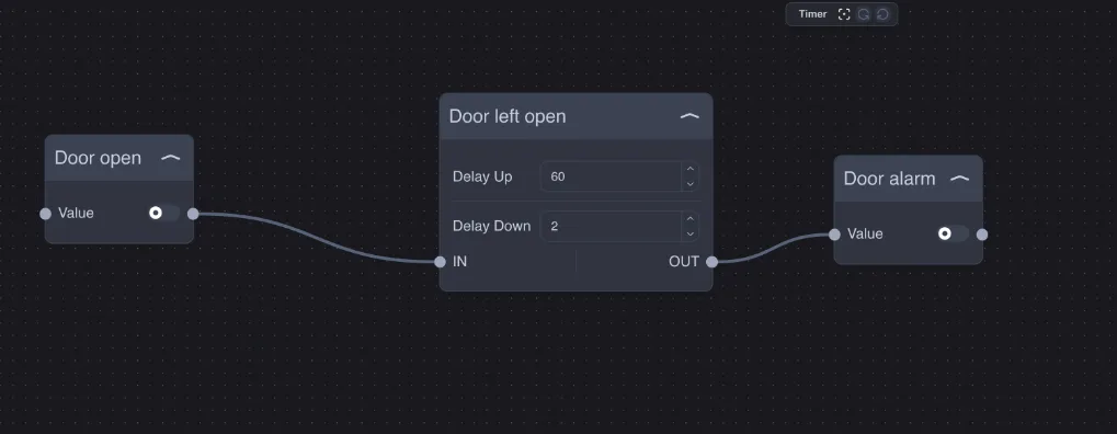
Delays changes on input IN:
when IN turns on, OUT turns on after Delay Up seconds;
when IN turns off, OUT turns off after Delay Down seconds;
if IN changes again before the delay ends, the current delay is canceled.
Delays are in whole seconds; an empty field means 1 second, 0 means immediately.
Example — door left open: with Delay Up = 60, the Door alarm alarm triggers only if the door stays open for a full minute: if you close it before then, nothing happens. Delay Down = 2 turns the alarm off two seconds after closing.
Other uses: bathroom fan that starts 2 minutes after the light turns on and stops 5 minutes after it turns off; filter against false alarms from a sensor that turns on briefly.
Stairs Light
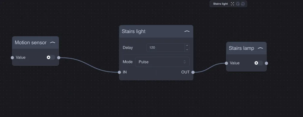
Turns the output on and switches it off automatically after Delay seconds (default 60). The Mode property determines how time is counted:
Mode | Operation | For |
|---|---|---|
Presence | The light stays on while the input is on; the countdown starts when the input turns off. | Presence sensors that stay on while someone is there. |
Pulse | Each time the input turns on, the countdown restarts from zero; input off is ignored. | Pushbuttons and motion sensors that send short pulses. |
The command is sent to the light only when the state changes: continuous detections do not flood the bus with "on" commands.
Example — stair light: a motion sensor in Pulse mode with Delay = 120: the light stays on for two minutes after the last movement.
Trigger
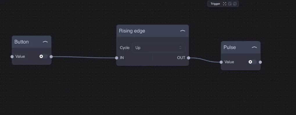
Turns an edge into a pulse (on and immediately off) on output OUT. The Cycle property selects the edge:
Up: pulse when the input changes from off to on;
Down: pulse when the input changes from on to off.
Example: a switch that stays on must start a scenario that needs a pulsed command; or "when the sun sets" (Down edge of the Astronomy Clock).
Numeric Trigger
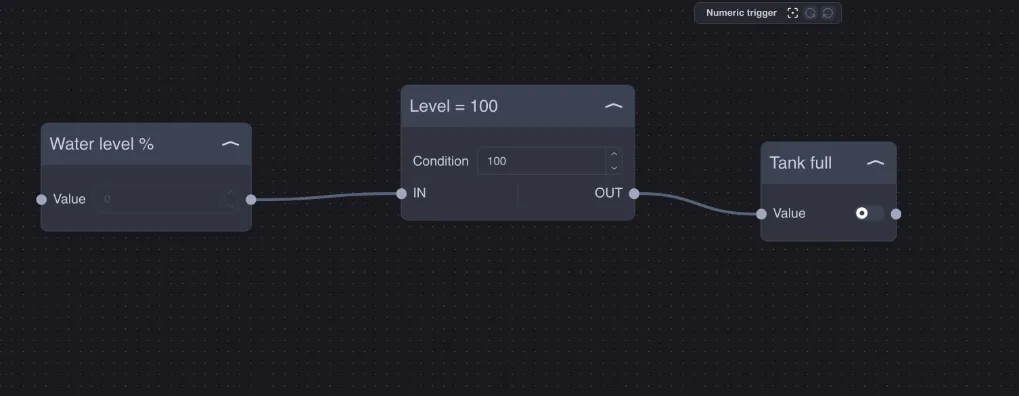
Sends a pulse on OUT when the number on input IN becomes equal to Condition.
Example — tank full: when the water level reaches 100%, the Tank full pulse is generated, which can stop the pump or send a notification.
For a threshold (greater than, less than) use an IF followed by a Trigger.
Astronomy Clock
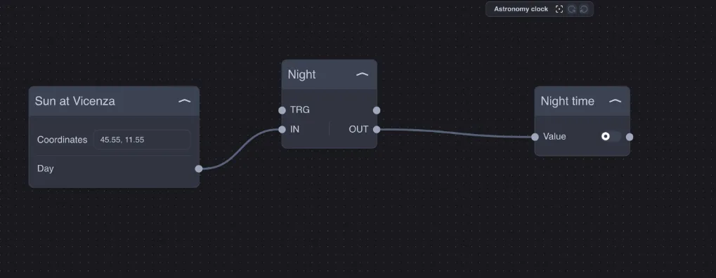
Calculates sunrise and sunset for the plant location: output Day is on during the day and off at night. The calculation updates every 10 seconds.
Enter latitude and longitude in Coordinates, separated by a comma, with a decimal point: for example 45.55, 11.55 for Vicenza. Coordinates can be found on any map (in Google Maps, right-click on the point).
Check the coordinates carefully: if the field is empty or entered incorrectly, the node uses point 0, 0 (in the Atlantic Ocean, on the equator) and sunrise and sunset will be wrong without any warning. After changing the coordinates, reload the flows with Upload.
Typical uses: shutters that close at sunset, garden lights on only at night, signs off during the day.
Date/Hour
Provides the server date and time, updated every second:
Output | Value |
|---|---|
Seconds, Minute, Hour | Seconds (0–59), minutes (0–59), hours (0–23). |
Day, Month, Year | Day of the month, month (1–12), year. |
Week | Week number of the year. |
Weekday | Day of the week in English: |
Daylight Savings | On when daylight saving time is in effect. |
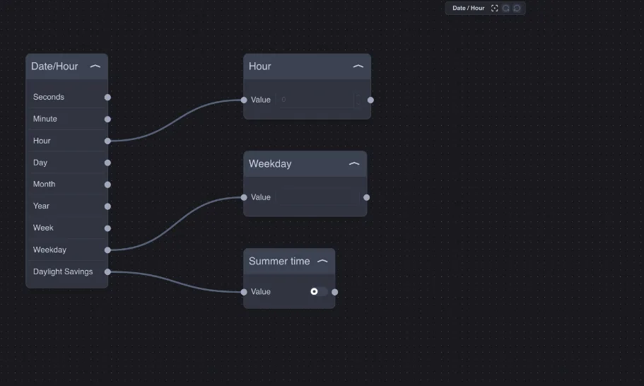
Example — time scheduling: an IF Equal between Hour and the number 7 turns the heating on at 7; a second IF Equal between Weekday and the text Sunday excludes Sunday.
The outputs of Date/Hour are sent every second, even if the value does not change. Place an IF and a Trigger before a command to the system, so the command is sent only once.
Repeat Command
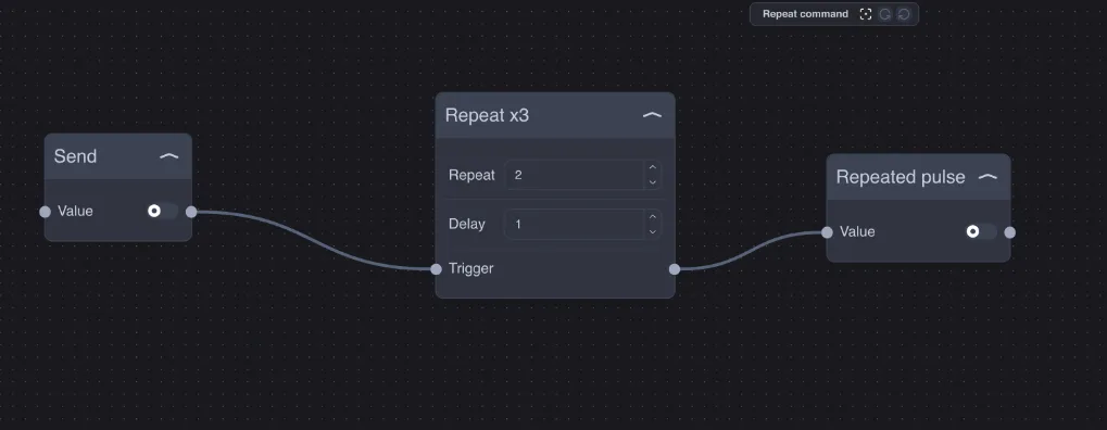
When the Trigger input turns on, the Trigger output sends a series of pulses: the first immediately, then another Repeat pulses, spaced Delay seconds apart. With Repeat = 2, a total of 3 pulses are output.
Example: repeat a command to a radio device that sometimes does not receive the first signal, or a sound signal repeated three times.
Oscillator and Clock
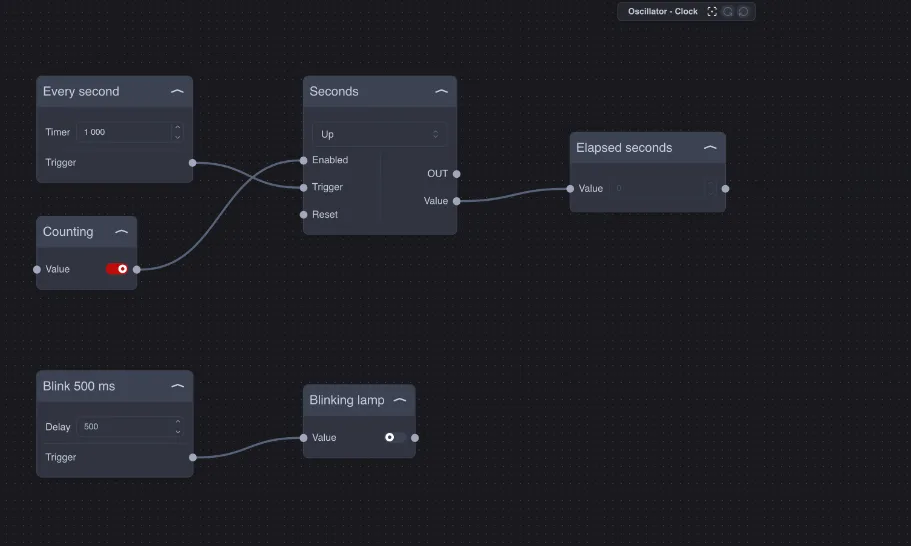
They generate a continuous signal, with no inputs, from the moment the flow starts:
Oscillator sends an pulse on the Trigger output every Timer milliseconds (minimum 100);
Clock switches on and off on the Trigger output every Delay milliseconds (from 100 to 100,000, default 1000).
Example: the Oscillator at 1000 ms connected to a Counter counts the elapsed seconds; the Clock at 500 ms makes an alarm indicator blink.
Do not connect Oscillator and Clock with short times directly to plant components: each pulse becomes a bus command. Use them for counting, for making virtual indicators blink, or with long times.
Counter
Counts the rising edges of the Trigger input and places the count on the Value output.
Property / input | Meaning |
|---|---|
Enabled | The counter counts only when it is on. |
Trigger | Each transition from off to on counts as one increment. |
Reset | Resets the count to the Preset value. While it remains on, counting is stopped. |
Preset | The starting value (default 0): with Preset = 0, the first event gives 1. |
Up / Down | Counts up or down. |
OUT | A pulse at each count. |
Value | The current count. |
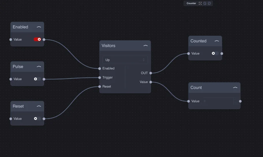
Example — people counter: a photocell at the shop entrance on Trigger, the count on an app Info component, Reset at 00:00 with the Date/Hour node.
Other uses: with Down and Preset = 10, a countdown of available entries; with an IF on the Value output, maintenance every 500 pump cycles.