
Vimar Gateway: parameters
Configure Vimar By-me on X1 Plus and import the XML database: gateway parameters, components, KNX virtual feedback, addresses and CSV, with Manager images.
The Vimar gateway connects X1 Plus to the Vimar By-me system. First configure the bus connection, then associate each component with its corresponding device and the function to be controlled.
The English names correspond to the Manager fields. To fill in the addresses, use the By-me configuration data for your system.
Gateway properties
Open Gateways and create or select the Vimar gateway.
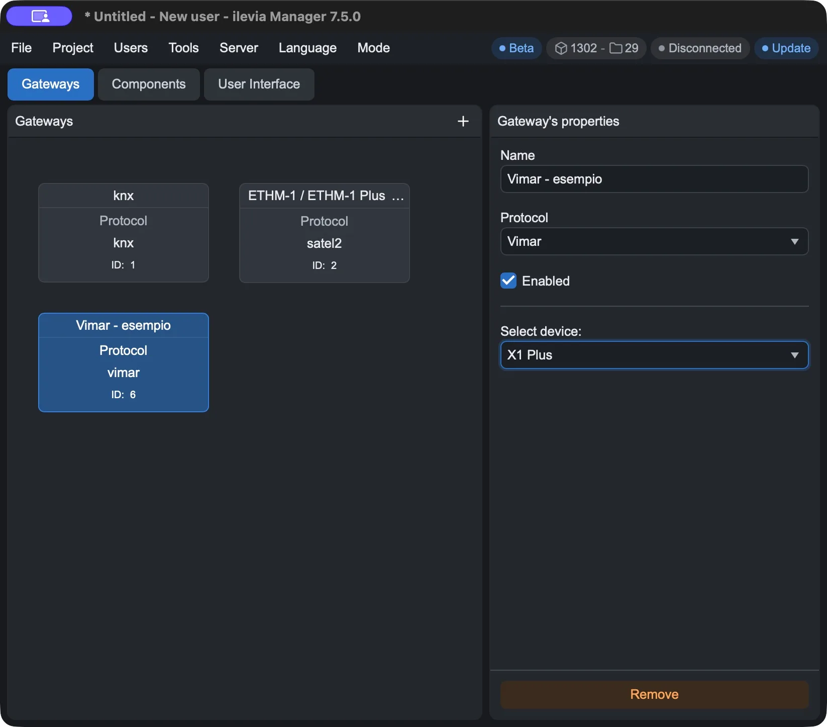
Assign a recognizable Name, choose Vimar in Protocol and leave Enabled active.
For the integrated connection in the example, set Select device = X1 Plus.
With X1 Plus selected, you do not need to enter an IP address or a port. The Manager shows the fields relevant to the selected connection type: in the integrated example these parameters do not appear.
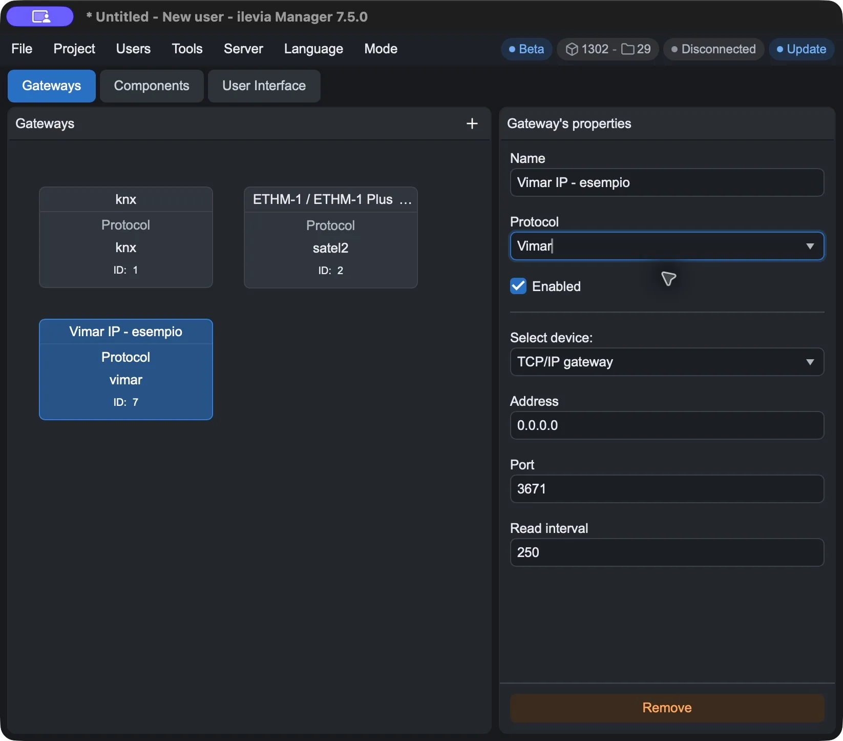
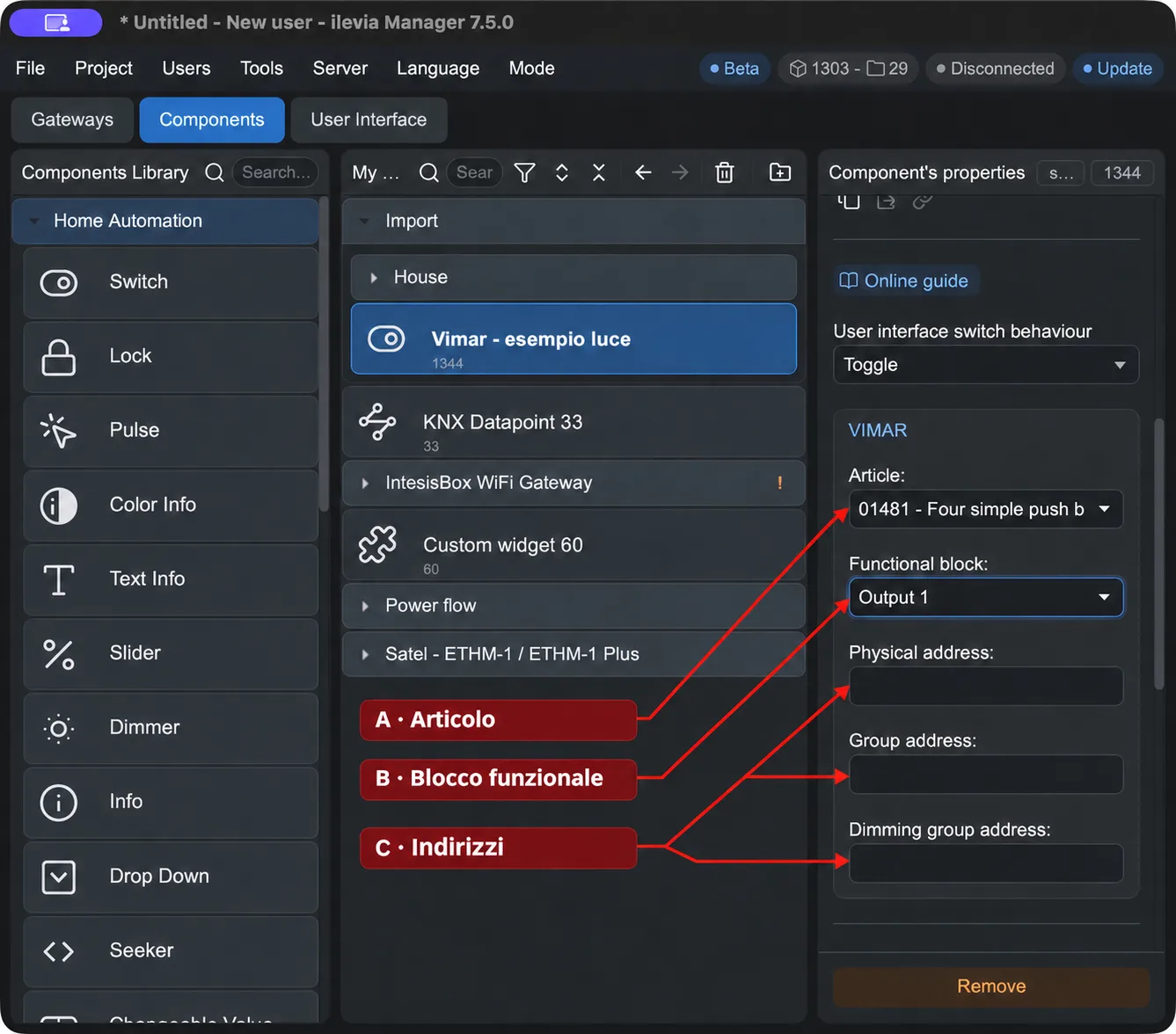
From left to right: integrated X1 Plus connection, connection via IP interface and component parameters with arrows A–C. Click the images to enlarge them.
Field | Meaning |
|---|---|
Name | Gateway name in the project, used to identify it when associating it with components. |
Protocol | Select Vimar. |
Enabled | Enable or disable the gateway. |
Select device | Select the connection actually used. The example in this guide uses X1 Plus. |
Connection via IP interface or USB/serial
The fields change with Select device. Do not enter a serial path in the IP field, and do not confuse the connection address with the physical address of the Vimar device configured in the component.
Mode / Field | Configuration |
|---|---|
TCP/IP gateway · Address | IP address of the Vimar interface defined by the system configuration. The initial value 0.0.0.0 must be replaced. |
TCP/IP gateway · Port | Port of the interface. In the Manager the initial value is 3671: use the port defined by its configuration. |
TCP/IP gateway · Read interval | Interval between group reads, in milliseconds. The initial value is 250 ms. |
USB/Serial · Serial device | Path of the device serial port, for example /dev/ttyS1. This is a local path, not an IP address. |
USB/Serial · Serial Physical address | Physical address of the connection when required by this mode. The field appears in the USB/Serial mode verified in the Manager. |
Integrated X1 Plus | Select X1 Plus. In the integrated connection screen, the IP, port and serial path fields do not appear. |
To create or remove a gateway, see Adding and removing a gateway.
Component parameters
Open Components and select the component to configure, for example Switch for an ON/OFF light.
In the Gateway field, associate the Vimar gateway configured for X1 Plus.
Scroll to the VIMAR section. First choose Article, then Functional block and fill in the system addresses.
Field | How to use it |
|---|---|
A · Article (Article) | Select the code and type of the Vimar device to be controlled. The choice determines the available functional blocks. |
B · Functional block (Functional block) | Select the output or function of the device to associate with the component. In the screen shown, article 01481 offers Output 1. |
C · Physical address (Physical address) | Address of the device in the By-me system. Enter the one from the system configuration. |
C · Group address (Group address) | Group address associated with the function to be controlled. This is not the gateway IP address and must not be confused with the physical address. |
C · Dimming group address | Dedicated group address for brightness adjustment, when the controlled function is dimmable. For a simple ON/OFF function, there is no need to enter a dimming address. |
Example: an ON/OFF light
The example shows a Switch component with Article = 01481 and Functional block = Output 1. It is a reference for identifying the fields: choose the actually installed article and enter its addresses. In the screen the addresses are left blank because they depend on your system.
If you have the By-me database, you can also refer to Importing the Vimar By-me database (.xml).
Importing the Vimar By-me database
If you have the system database, you can import it instead of configuring all components manually. The procedure uses the XML file exported from EasyTool Professional for WebServer.
The import represents the By-me devices in the Ilevia project and creates the KNX associations provided by the importer. Virtual feedback also allows you to manage By-me functions that do not have a direct KNX match: the conversion concerns the project configuration.
1. Exporting the system from EasyTool Professional
Open Vimar EasyTool Professional.
Select File → Open system and open the system database you need.
Select File → Export → WebServer.
Choose where to save the WebServer (.xml) file. The file to import in the Manager is this XML, not the original EasyTool database.
2. Open the importer in the Manager
Open the Ilevia project where you want to add the devices.
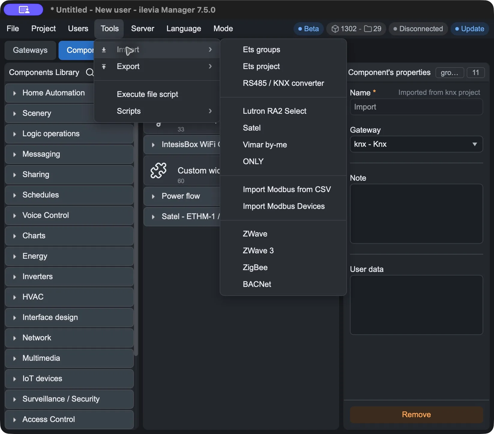
Select Tools → Import → Vimar by-me (Tools → Import → Vimar By-me).
In the Import VIMAR By Me window, fill in the fields described below.
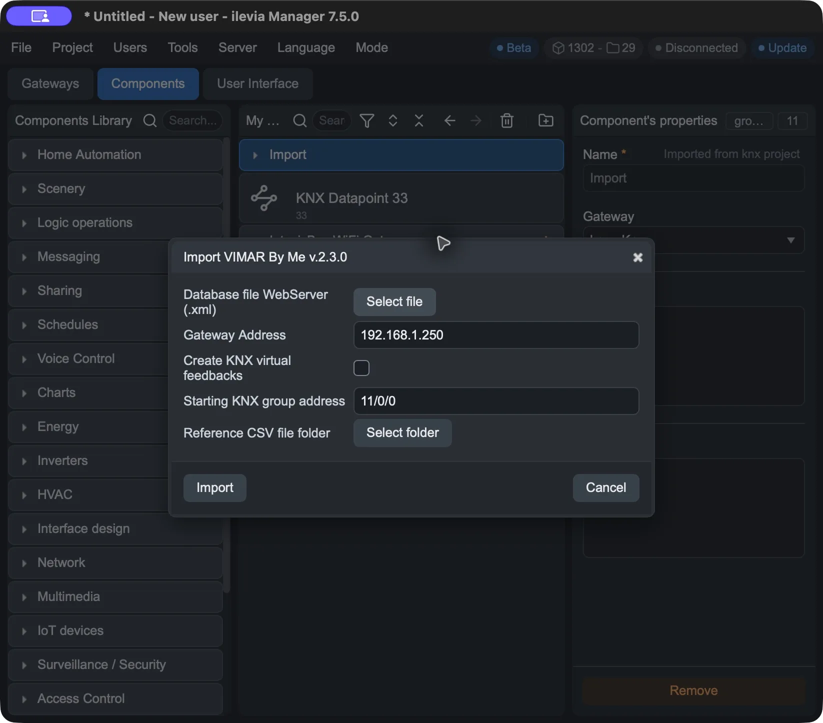
3. Fill in the import parameters
Field | How to use it |
|---|---|
Database file WebServer (.xml) / Select file | Select the XML file exported from EasyTool Professional. |
Gateway Address | Enter the Vimar gateway IP address, as specified by the existing import procedure. The 192.168.1.250 value shown in the window is an example: use the address assigned to the system. |
Create KNX virtual feedbacks | Enable this option if you want to create KNX read and write references for By-me functions that do not have a direct KNX match. |
Starting KNX group address | KNX group address from which assignment starts. The window proposes 11/0/0: choose a free range consistent with the project. |
Reference CSV file folder / Select folder | Choose the folder where the reference CSV will be saved. The file will contain the KNX group addresses of the imported By-me devices. |
Import / Cancel | Import starts the import into the current project; Cancel closes the window without importing. |
4. Verify the imported devices
Confirm with Import only after checking the file and parameters. According to the By-me database procedure, the gateway is added to the project and enabled; the devices are inserted and organized automatically.
Compare the devices and the structure of the imported project with those in the EasyTool database.
Check the created gateway and the actual connection type used by X1 Plus, referring to the parameters described above.
Verify the association of the components with the gateways and check the addresses in the reference CSV.
Check the functions that require virtual feedbacks before applying the project to the server.
Keep the XML file and the CSV: they allow you to compare the By-me configuration with the addresses used in the Ilevia project. After these checks, save and upload the project to X1 Plus, as described in the next section.
Apply the changes and verify
Save the project with File → Save.
Upload the project to X1 Plus with Project → Upload. Repeat the upload whenever you want to apply new changes to the server.
Send a command from the control interface and verify that it acts on the expected output and that the component value is updated correctly.
If it does not respond, check Enabled, the gateway associated with the component, and the bus connection. If a different output responds, check Article, Functional block, and the By-me addresses.