Create, save and upload flows
How to create a flow, add and connect nodes, add inputs and outputs, save the work to a file, upload flows to the server with Upload, download them with Download, test them, and read the logs.
This page explains the complete workflow: from an empty flow to a flow running on the server. For the editor sections, see The Flow editor.
The first flow, step by step
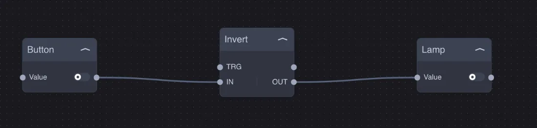
The simplest example: a button that switches a lamp the other way around (button pressed = lamp off). You can find it in the Getting started flow of the sample project.
Step 1. Create the flow. Press + to the right of the tabs. In the Properties window, enter the flow name (Flow name) and, if needed, a description (Flow description) explaining what it is for.
Step 2. Add the nodes. From the Operators window, add a Switch node from the Dummies category (this will be the button), a NOT node from the Boolean category, and a second Switch (this will be the lamp). Double-click the item or drag it onto the canvas. In your installation, instead of the Dummy components, drag the real components from the Components window.
Step 3. Name the nodes. Select each node and change the Name field in the Properties window: Button, Invert, Lamp. Clear names keep the flow readable even after months.
Step 4. Connect the nodes. Drag from the button's output dot (on the right) to the NOT IN dot, then from the NOT OUT output to the lamp's input dot Value. A wire always goes from an output to an input.
Step 5. Save and upload. Save a copy to file with Save As, then press Upload to send the flows to the server. From that moment on, the server runs the logic even with the editor closed.
Additional inputs and outputs
Some nodes have a variable number of inputs or outputs: AND, OR, XOR, Math, Javascript, Sequencer, Scenario, Numeric Encoder, and Decoder. The green Add button (on the left for inputs, on the right for outputs) adds an item: IN 1, IN 2… or OUT 1, OUT 2… In Sequencer, each new output carries its delay with it (DELAY 1, DELAY 2…).
Connections: the rules
An output can drive multiple inputs: for example, the same sensor can feed three different logic blocks.
An input should receive only one wire: if two wires reach the same input, the last value received takes precedence.
To delete a wire, select it with a click and press Backspace. To delete a node, select it and press REMOVE in the Properties window.
Types must make sense: a numeric output (for example, a temperature) sent to a Boolean input is converted (0 = off, any other number = on); non-numeric text sent to a Number input does not produce a valid value.
Saving to file: Save As and Open File
Save As downloads a .json file to the computer with all the open flows: nodes, connections, properties, names, notes, and viewport position. Open File loads a saved file and opens its flows in tabs.
The file is useful for:
keeping a backup before major changes;
moving the same logic from one installation to another (then replace the components);
preparing the logic in the office and loading it on site.
Opening a file does not affect the server. The server changes only when you press Upload.
Uploading to the server: Upload
Upload sends all flows currently in the editor to the server. The server saves them, starts them, and returns the result in Logs. After uploading, the modified markers on the tabs disappear.
Upload replaces all flows on the server with those in the editor: a flow that exists on the server but not in the editor is deleted. Before working on an already configured installation, always press Download and keep a copy with Save As.
Downloading from the server: Download
Download loads into the editor the flows currently saved on the server, replacing the ones open in the editor. Use it at the beginning of each work session so you edit the latest version, not an old copy.
Testing flows
The Start simulation button (Play) starts execution and shows values in real time on the nodes: you can manually change an input (for example, turn on a Dummy Switch) and see how the other nodes react. When flows are stopped, value fields are read-only.
How the server runs flows:
when a flow starts, each wire immediately transmits the current value of its output, so the nodes start from a consistent state;
every value change is propagated along the wires up to the last node in the chain;
a stopped flow remains saved on the server but does not react to events;
flows run on the server: they keep working with the editor closed, with the computer turned off, and even without Internet.
Reading the logs
The Logs window (terminal icon or Logs button at the bottom) collects server messages: Upload and Download results, node configuration errors, warnings. Click the flow name in a row to open it. A message such as Simulator not found means that you requested the values of a flow that has not yet been loaded or started on the server.