
Vimar-gateway: parameters
Configure Vimar By-me on X1 Plus and import the XML database: gateway parameters, components, KNX virtual feedback, addresses and CSV, with Manager images.
The Vimar gateway connects X1 Plus to the Vimar By-me system. First configure the bus connection, then associate each component with the related device and the function to be controlled.
The English names correspond to the Manager fields. To fill in the addresses, use the By-me configuration data of your system.
Gateway properties
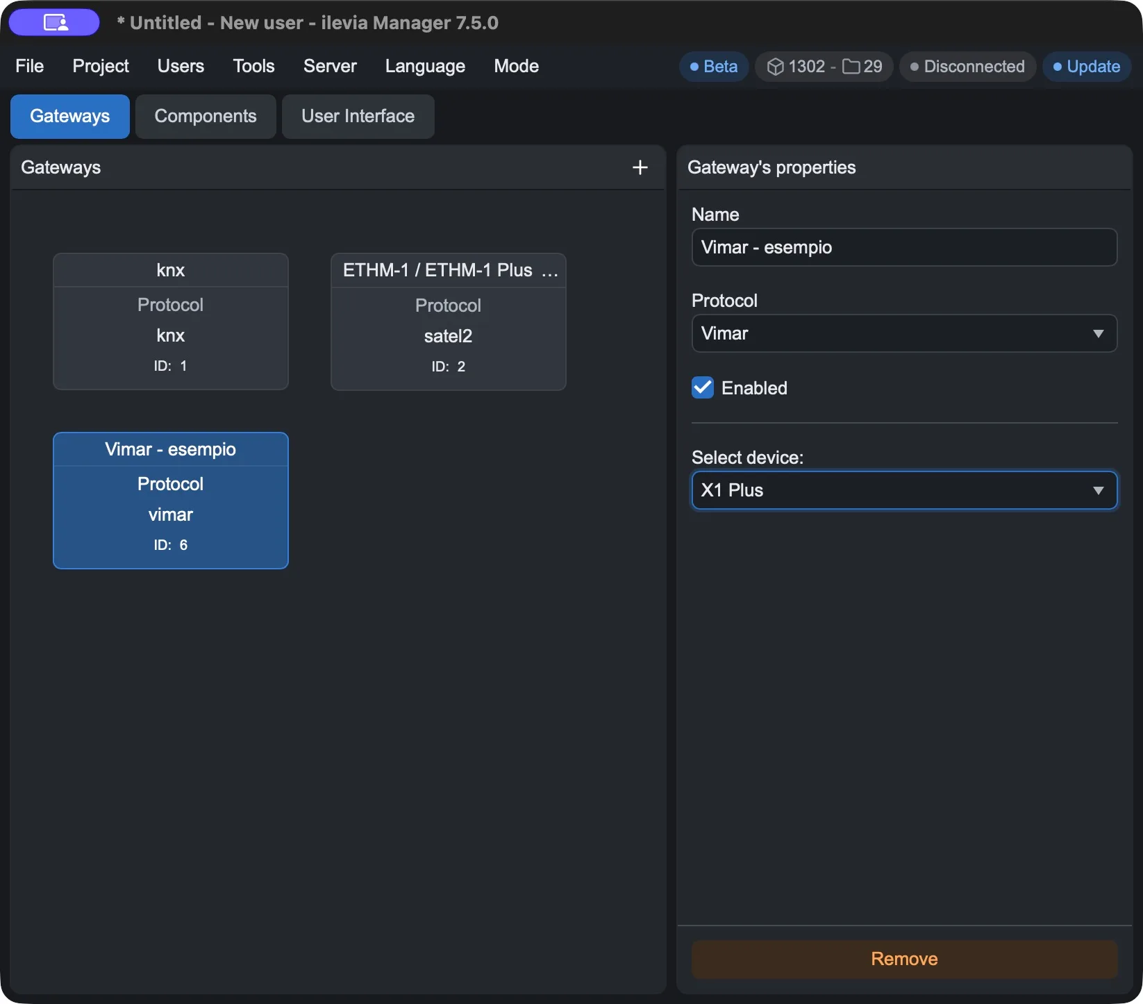
Open Gateways and create or select the Vimar gateway.
Assign a recognizable Name, select Vimar in Protocol and leave Enabled active.
For the integrated connection in the example, set Select device = X1 Plus.
With X1 Plus selected, you do not need to enter an IP address or a port. The Manager shows the relevant fields for the selected connection type: in the integrated example these parameters do not appear.
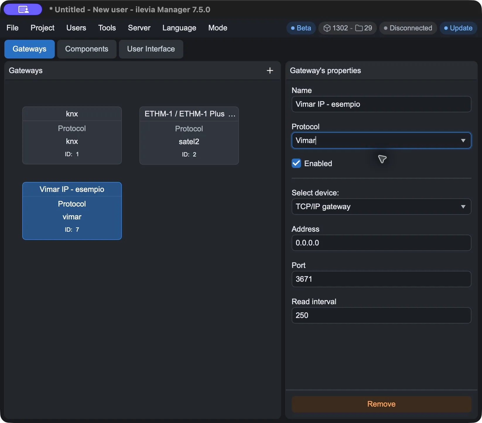
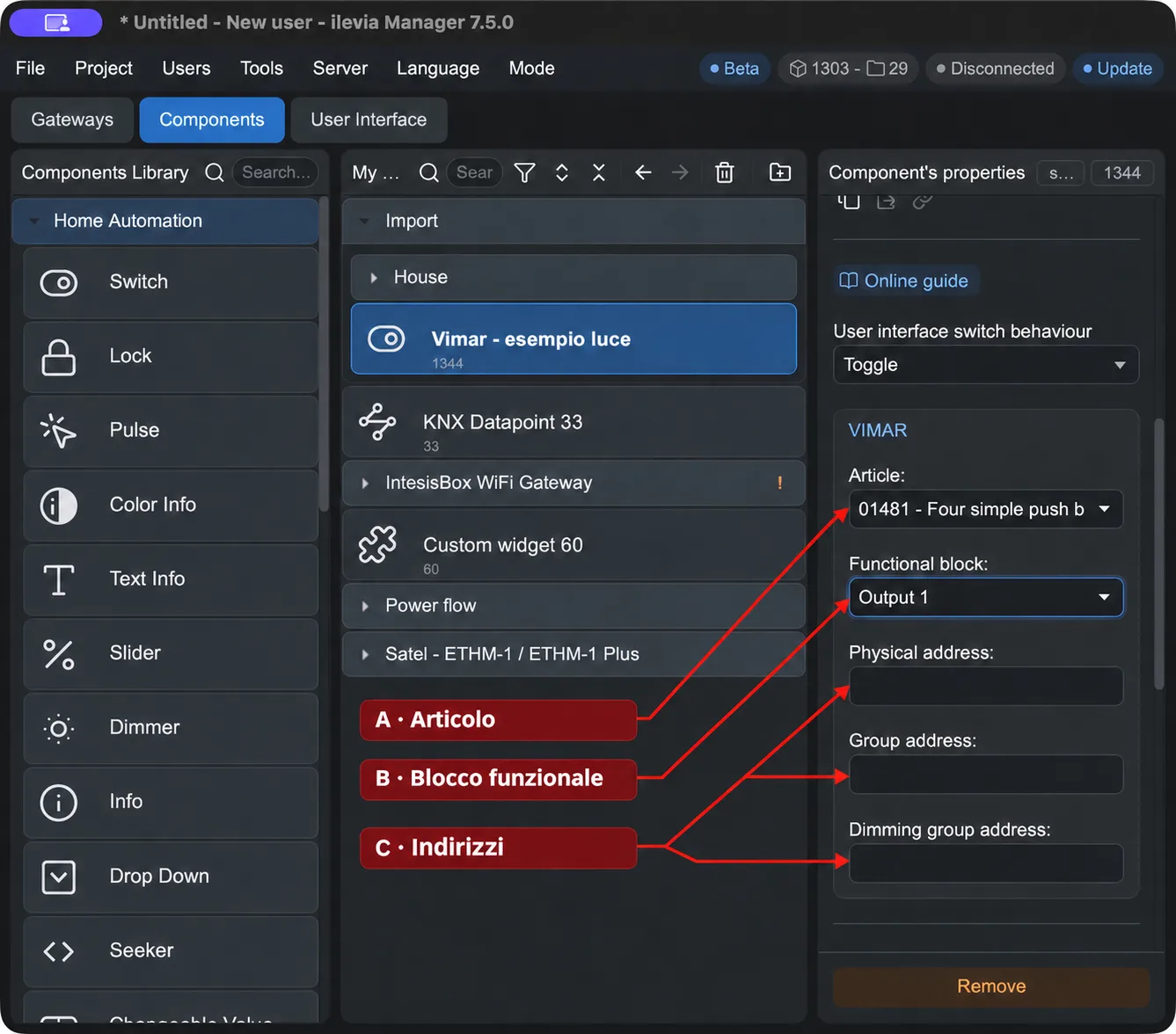
From left: X1 Plus integrated connection, connection via IP interface, and component parameters with arrows A–C. Click the images to enlarge them.
Field | Meaning |
|---|---|
Name | Gateway name in the project, to recognize it when you associate it with the components. |
Protocol | Select Vimar. |
Enabled | Enable or disable the gateway. |
Select device | Select the connection actually used. The example in this guide uses X1 Plus. |
Connection via IP or USB/serial interface
The fields change with Select device. Do not enter a serial path in the IP field and do not confuse the connection address with the physical address of the Vimar device configured in the component.
Mode / Field | Configuration |
|---|---|
TCP/IP gateway · Address | IP address of the Vimar interface defined by the system configuration. The initial value 0.0.0.0 must be replaced. |
TCP/IP gateway · Port | Port of the interface. In the Manager the initial value is 3671: use the port defined by its configuration. |
TCP/IP gateway · Read interval | Interval between group reads, in milliseconds. The initial value is 250 ms. |
USB/Serial · Serial device | Serial port path of the device, for example /dev/ttyS1. This is a local path, not an IP address. |
USB/Serial · Serial Physical address | Physical address of the connection when this mode requires it. The field appears in the USB/Serial mode verified in the Manager. |
Integrated X1 Plus | Select X1 Plus. In the integrated connection screen, the IP, port or serial path fields do not appear. |
To create or remove a gateway, see Add and remove a gateway.
Component parameters
Open Components and select the component to configure, for example Switch for an ON/OFF light.
In the Gateway field, associate the Vimar gateway configured for X1 Plus.
Scroll to the VIMAR section. First choose Article, then Functional block and fill in the system addresses.
Field | How to use it |
|---|---|
A · Article | Select the code and type of the Vimar device to control. The choice determines the available functional blocks. |
B · Functional block | Select the output or function of the device to associate with the component. In the screen the article 01481 offers Output 1. |
C · Physical address | Address of the device in the By-me system. Enter the one from the system configuration. |
C · Group address | Group address associated with the function to be controlled. It is not the gateway IP address and must not be confused with the physical address. |
C · Dimming group address | Dedicated group address for brightness adjustment, when the controlled function is dimmable. For a simple ON/OFF function, it is not necessary to fill in a dimming address. |
Example: an ON/OFF light
The example shows a Switch component with Article = 01481 and Functional block = Output 1. It is a reference for identifying the fields: choose the actually installed article and enter its addresses. In the screen the addresses are left blank because they depend on your system.
If you have the By-me database, you can also consult the guide Importing the Vimar By-me database (.xml).
Importing the Vimar By-me database
If you have the system database, you can import it instead of configuring all components manually. The procedure uses the XML file exported from EasyTool Professional for WebServer.
The import represents the By-me devices in the Ilevia project and creates the KNX associations defined by the importer. Virtual feedback also allows management of By-me functions that do not have a direct KNX match: the conversion concerns the configuration in the project.
1. Export the system from EasyTool Professional
Open Vimar EasyTool Professional.
Select File → Open system and open the database of the system concerned.
Select File → Export → WebServer.
Choose where to save the WebServer (.xml) file. The file to import into the Manager is this XML, not the original EasyTool database.
2. Open the importer in the Manager
Open the Ilevia project to which you want to add the devices.
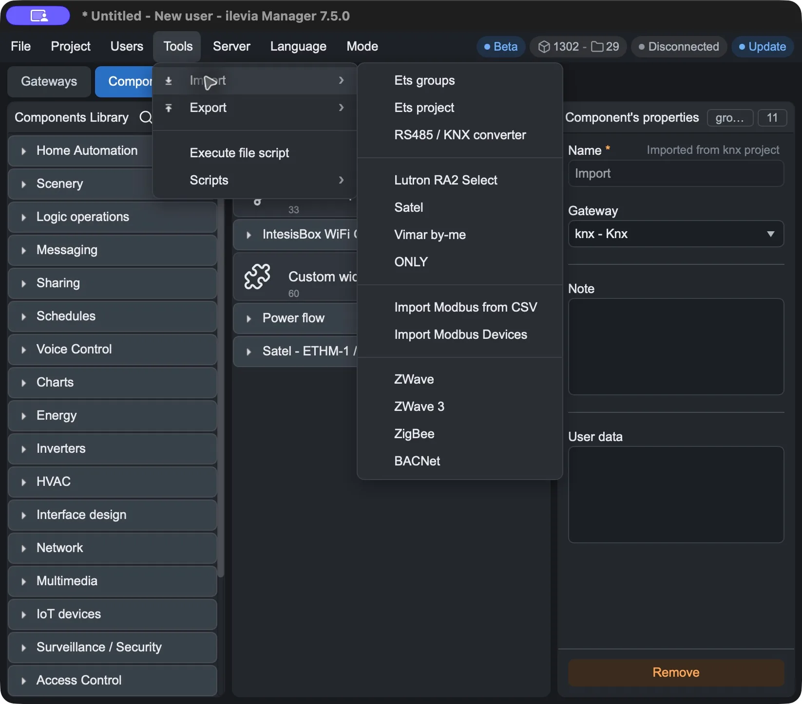
Select Tools → Import → Vimar by-me (Tools → Import → Vimar By-me).
In the Import VIMAR By Me window, fill in the fields described below.
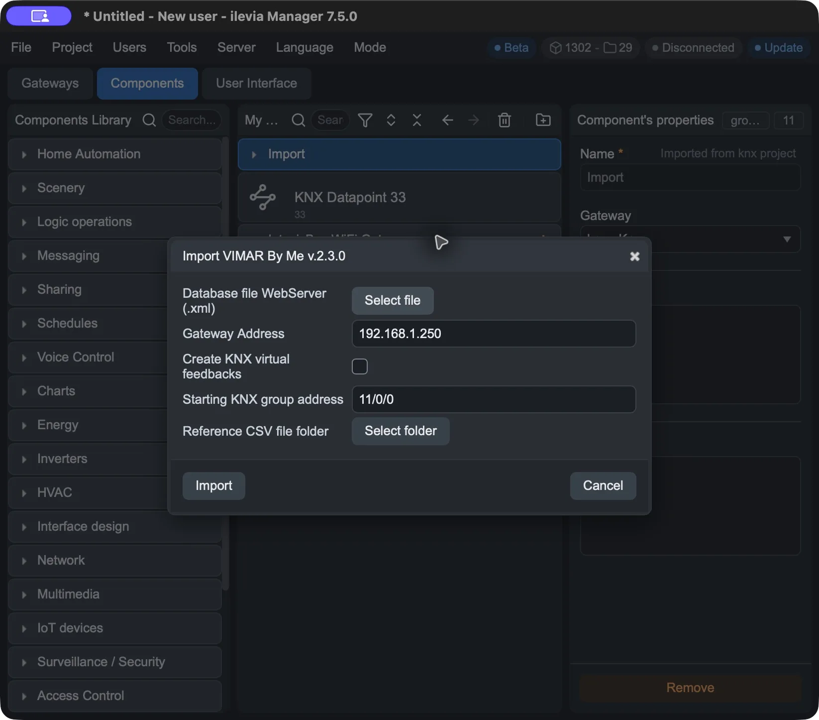
3. Fill in the import parameters
Field | How to use it |
|---|---|
Database file WebServer (.xml) / Select file | Select the XML file exported from EasyTool Professional. |
Gateway Address | Voer het IP-adres van de Vimar-gateway in, zoals voorzien in de bestaande importprocedure. De waarde 192.168.1.250 die in het venster wordt getoond, is een voorbeeld: gebruik het adres dat voor de installatie is voorzien. |
Maak KNX virtuele feedbacks aan | Schakel de optie in als u de KNX-referenties voor lezen en schrijven wilt aanmaken voor By-me-functies die geen directe KNX-overeenkomst hebben. |
Beginnende KNX-groepsadres | KNX-groepsadres vanaf welk de toewijzing moet beginnen. Het venster stelt 11/0/0 voor: kies een vrije reeks die past binnen het project. |
Map voor referentie-CSV-bestand / Map selecteren | Kies de map waarin u de referentie-CSV wilt opslaan. Het bestand bevat de KNX-groepsadressen van de geïmporteerde By-me-apparaten. |
Importeren / Annuleren | Importeren start de import in het huidige project; Annuleren sluit het venster zonder te importeren. |
4. De geïmporteerde apparaten controleren
Bevestig met Importeren pas nadat u het bestand en de parameters hebt gecontroleerd. Volgens de By-me-databaseprocedure wordt de gateway aan het project toegevoegd en ingeschakeld; de apparaten worden automatisch ingevoegd en geordend.
Vergelijk de apparaten en de structuur van het geïmporteerde project met die van de EasyTool-database.
Controleer de aangemaakte gateway en het type verbinding dat daadwerkelijk door X1 Plus wordt gebruikt, met verwijzing naar de hierboven beschreven parameters.
Controleer de koppeling van de componenten aan de gateways en controleer de adressen in de referentie-CSV.
Controleer de functies die virtuele feedback vereisen voordat u het project toepast op de server.
Bewaar het XML-bestand en de CSV: daarmee kunt u de By-me-configuratie vergelijken met de adressen die in het Ilevia-project worden gebruikt. Na deze controles slaat u het project op en laadt u het op X1 Plus, zoals beschreven in de volgende sectie.
Wijzigingen toepassen en verifiëren
Sla het project op via Bestand → Opslaan.
Laad het project naar X1 Plus via Project → Uploaden. Herhaal het uploaden telkens wanneer u nieuwe wijzigingen op de server wilt toepassen.
Geef een opdracht via de bedieningsinterface en controleer of deze de verwachte uitgang aanstuurt en of de waarde van het component correct wordt bijgewerkt.
Reageert het niet, controleer dan Enabled, de gateway die aan het component is gekoppeld en de busverbinding. Reageert een andere uitgang, controleer dan Article, Functional block en de By-me-adressen.