Switch
How to configure the Switch component in Ilevia Manager and how it appears in Ilevia Control, with Classic and Map views.
Introduction
The component can represent a sensor on/off state or control an actuator by changing the parameter value. It can be used as an input to an AND/OR logic, as a command to activate scenarios, or it can be controlled by weekly timers to generate events.
Use cases
With the switch component it is possible to interact with a physical object.
It can be used as an alarm trigger.
It can also be used as a trigger component for a scenario.
Component properties
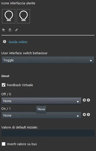
Icon and title can be customized as desired. We recommend referring to the guide “Common properties”.
Switch type: Lets you choose the function type of the switch (ON/OFF, Always ON, Always OFF).
Off / 0: This list of options lets you link a scenario that will be executed when the switch is set to Off.
On / 1: This list of options lets you link a scenario that will be executed when the switch is set to On.
Initial default value: This text field lets you set a value between 0 and 1 that will be assigned when the server starts.
Invert bus value: Lets you invert the value sent when the switch state changes.
KNX
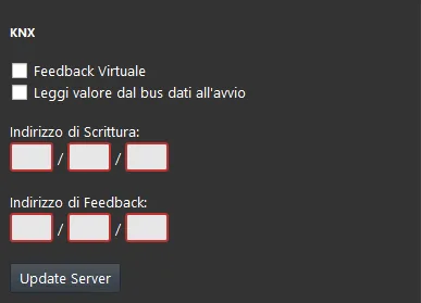
This component has been set up with the KNX gateway.
You can consult the guide “Gateway / protocols” for more information.
Virtual Feedback: see the guide “KNX protocol”;
Read data bus value at startup: see the guide “KNX protocol”;
Write / Feedback address: see the guide “KNX protocol”;
There are three possible display modes: “CLASSIC”, “MODAL” and “HIDDEN”. For more information, see the guide on “Common properties”.
Classic user interface
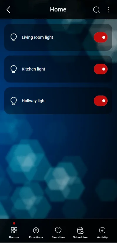
Here is the component result in Ilevia Control (Classic style).
Switches are shown as empty buttons that light up when selected.

Off state (white circle, Figure 1)

On state (blue circle, Figure 2)
Figure 1
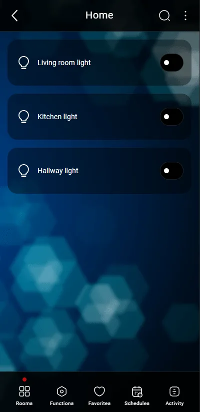
Figure 2
Map user interface
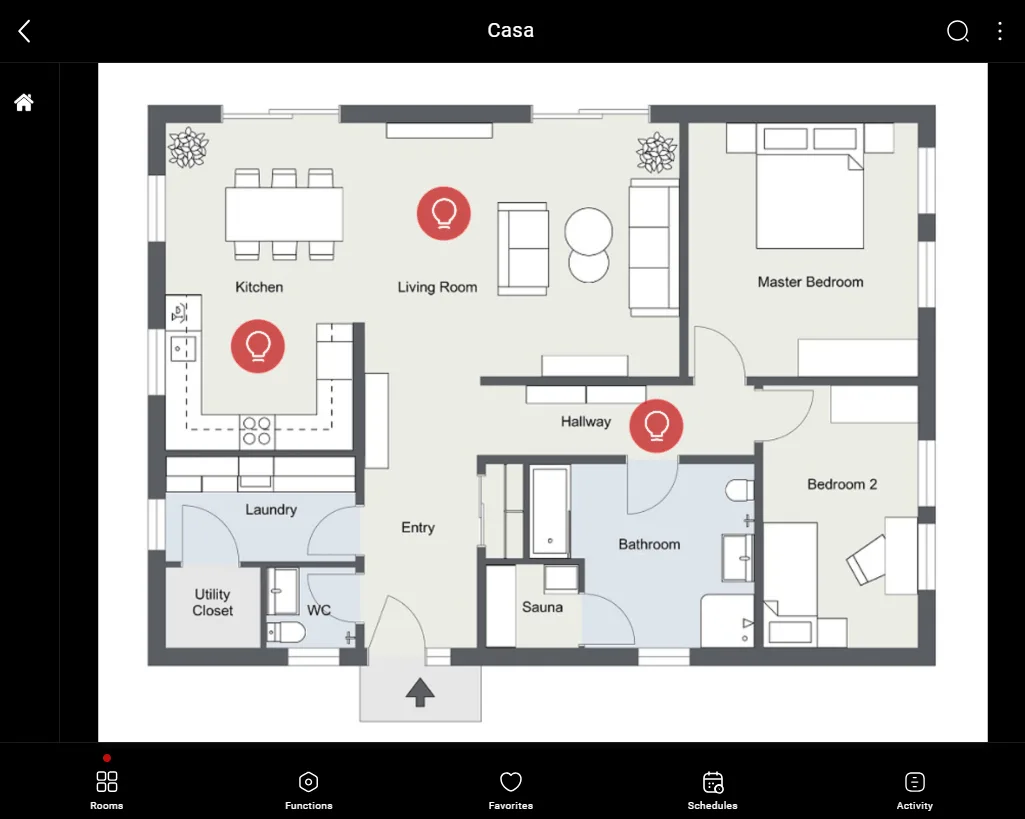
This is just one possible result of the component in Ilevia Control (in Map style).
The icon can be customized as needed, from the symbol to the color and size.
In this case, we see the switch in its two states, Off and On:

Off state (empty bulb, Figure 1)

On state (filled bulb, Figure 2)
Figure 1
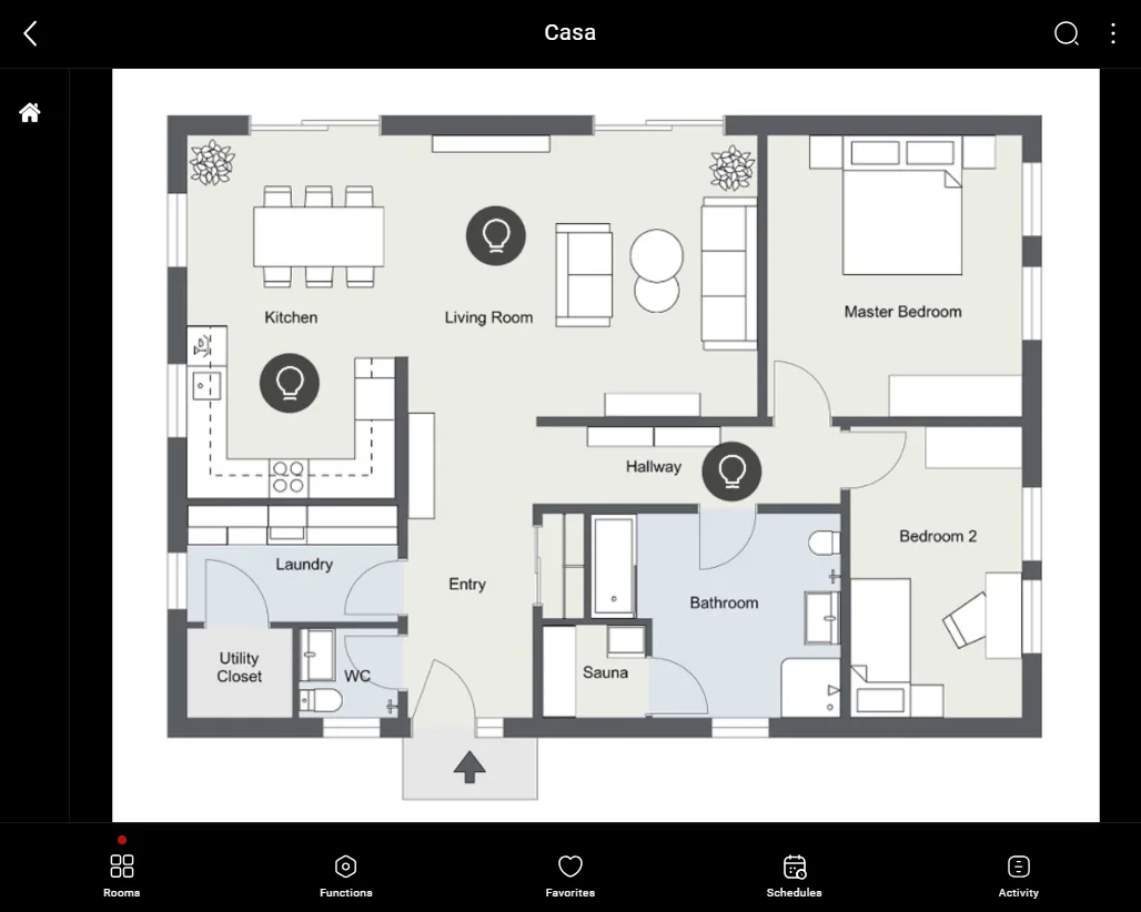
Figure 2