
Integration of Shelly i3 with the MQTT protocol
How to configure the Shelly i3 device via MQTT in Ilevia Manager to use up to 3 inputs, including with KNX actuators.
Introduction
The Shelly i3 device allows you to control up to 3 inputs at the same time. This guide explains how to configure it via the MQTT protocol in Ilevia Manager.
Use case
The user wants to set up 3 separate switches connected to the Shelly i3 device to use them with KNX actuators.
Step 1:
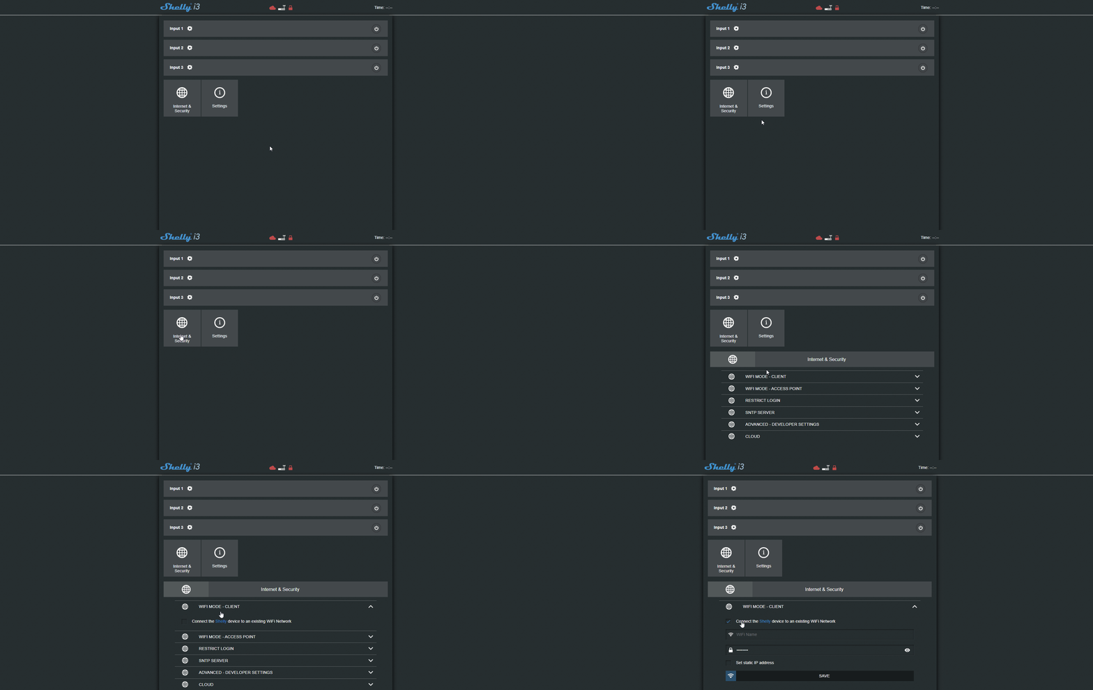
Turn on the device and connect to the Shelly i3 Wi-Fi network. Then open the web browser and enter the default IP address (192.168.33.1) to access the device configuration web interface.

Step 2:
To connect the Shelly device to your local network, go to the “Internet security settings” menu and open the “Wifi mode client” section.
Step 3:
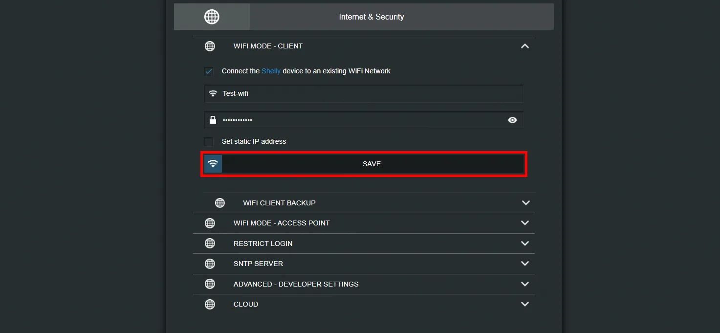
Enter your Wi-Fi network credentials and click Save. The device will attempt to connect to the network you entered.
Step 4:
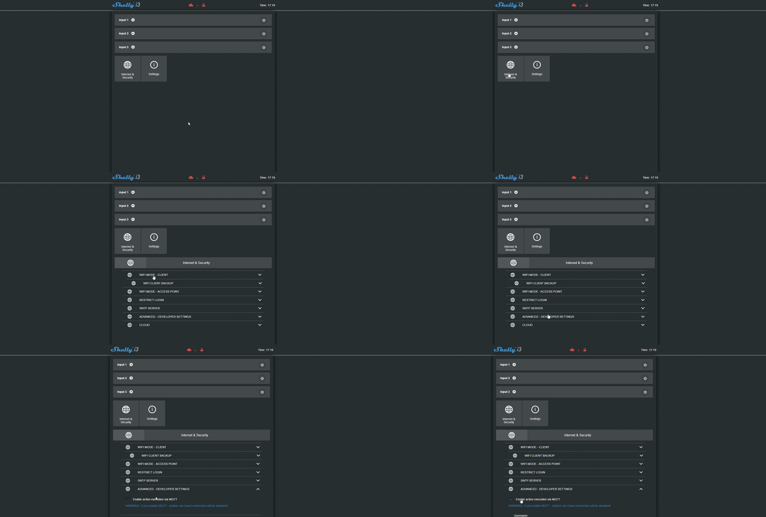
Reconnect to the web interface, now that the device is on your local network, and go to the “Internet and security settings” menu; then open the “Advanced developer settings” section and select the “Enable action execution via MQTT” checkbox.
Step 5:
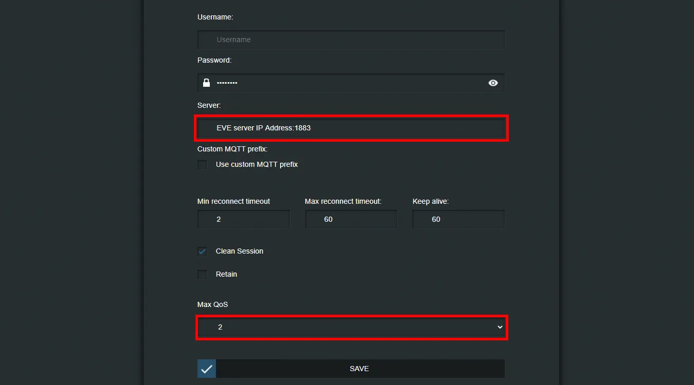
Once the “Advanced developer settings” option is enabled, configure the MQTT parameters to allow the Shelly device to communicate with the Ilevia server.
Enter the IP address of the server in the Ilevia server text field, set QoS to 2, and finally click Save.
NOTE:
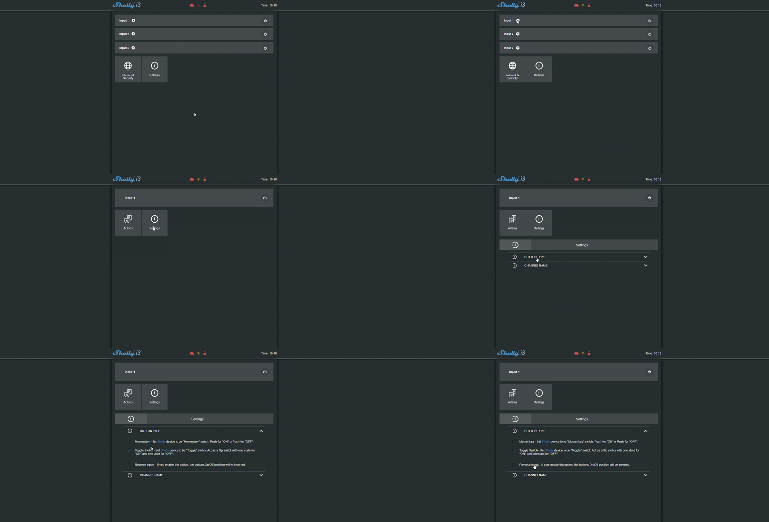
For this demonstration, the Shelly i3 device is set to toggle mode. To change this setting, open the input settings by clicking the gear icon next to the channel number (“channel”), then the “Settings” menu and finally the “Button type” section, where you can choose the button type.
Topic configuration
Step 6:
Open Ilevia Manager and create a new MQTT gateway in the Gateway section as explained in this guide.
Step 7:
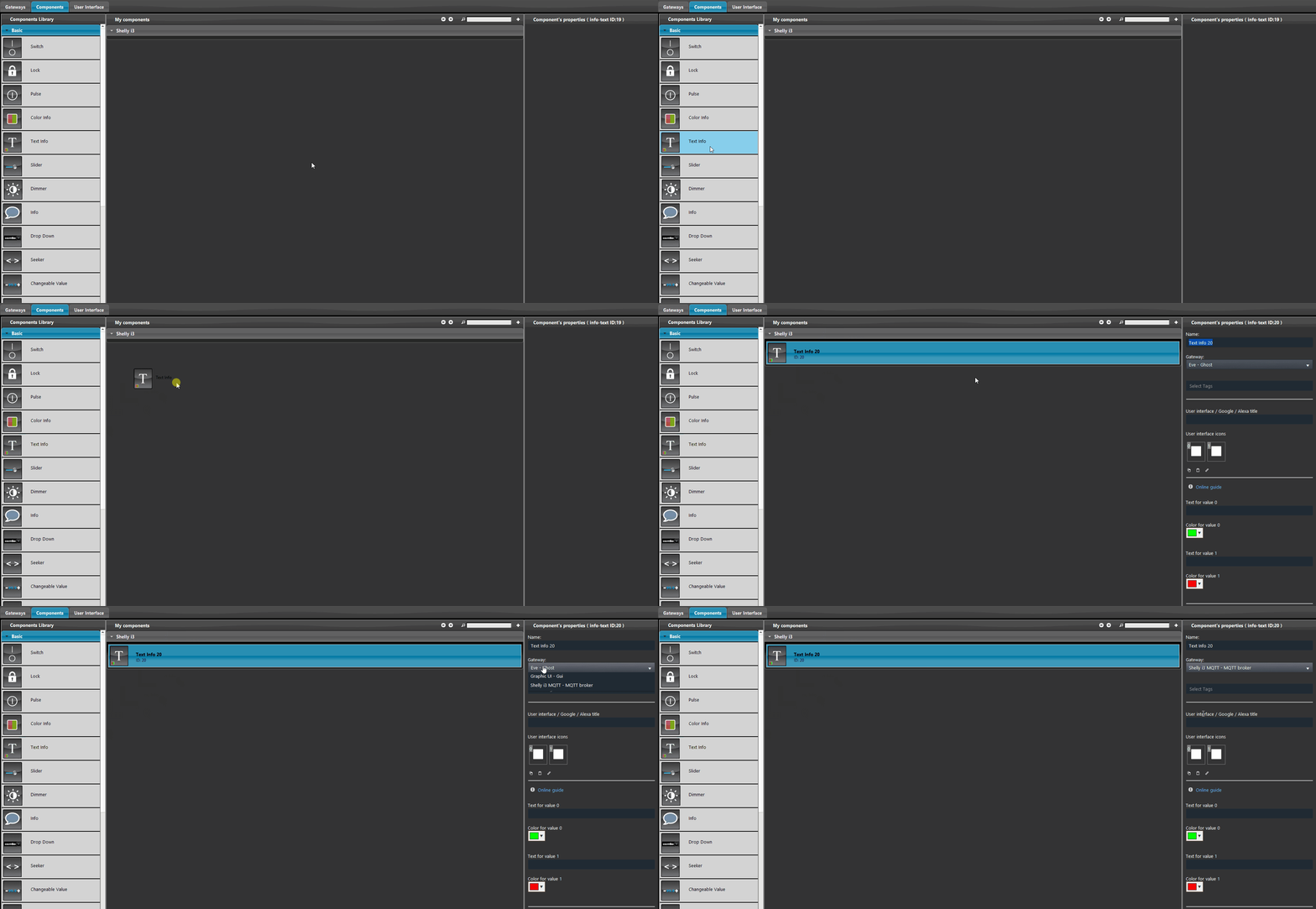
Now add the components to the project: go to the “My components” section and add up to three of the following components: Info, Text info, Colored info, and Switch, which you can find in the “Basic” section on the left side of the screen. Once the components have been added, in their settings select the MQTT gateway you created earlier from the list. In this guide we focus on channel L1.
Warning: in the Text info component it is mandatory to add two words in the component settings, in order to display the status in the user interface.
Step 8:
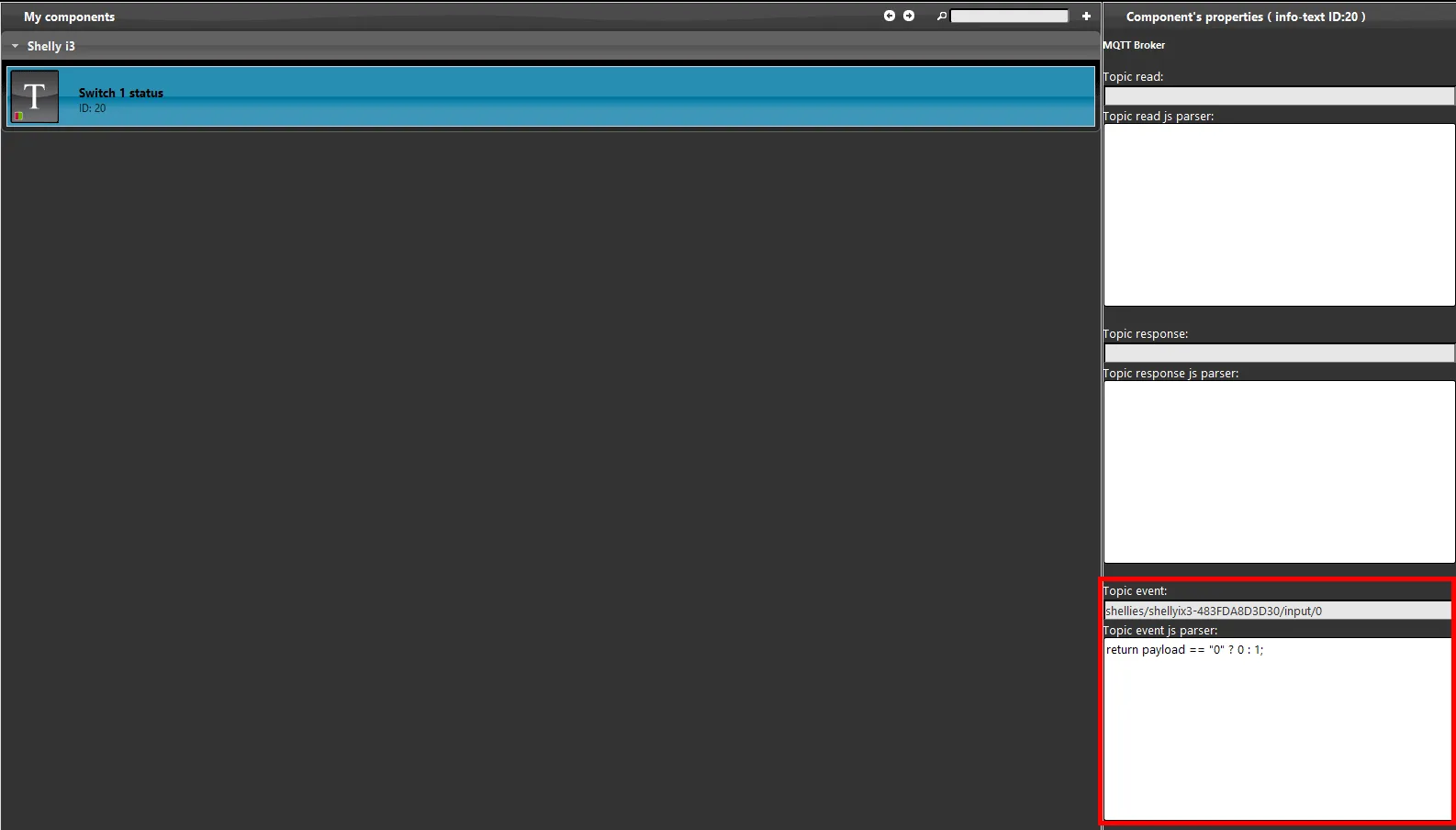
The topic configuration is divided by input channel: as mentioned at the beginning of the guide, you can configure up to 3 different switches, each with its own functions. Let’s start with the “Event” topic, which will be set with channel number “0”, corresponding to channel number 1 of the Shelly i3 device. The script below reads the status coming from the Shelly device.
Click this link to view the topics shown in the image below.
Visual result in the user interface
Step 9:
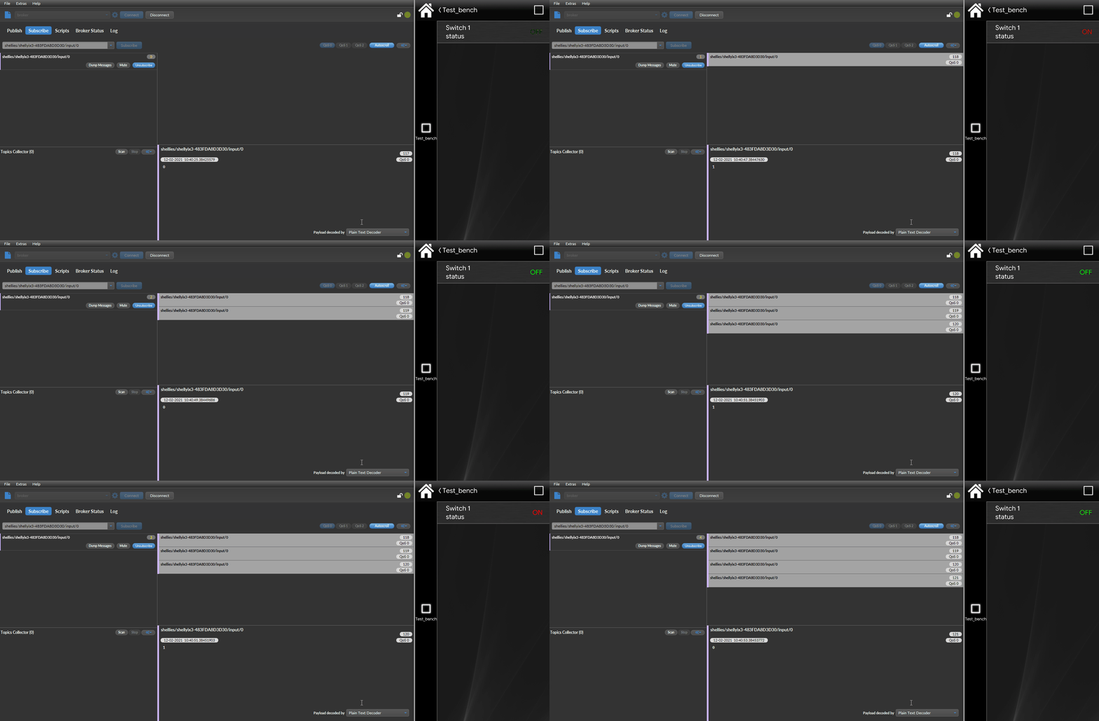
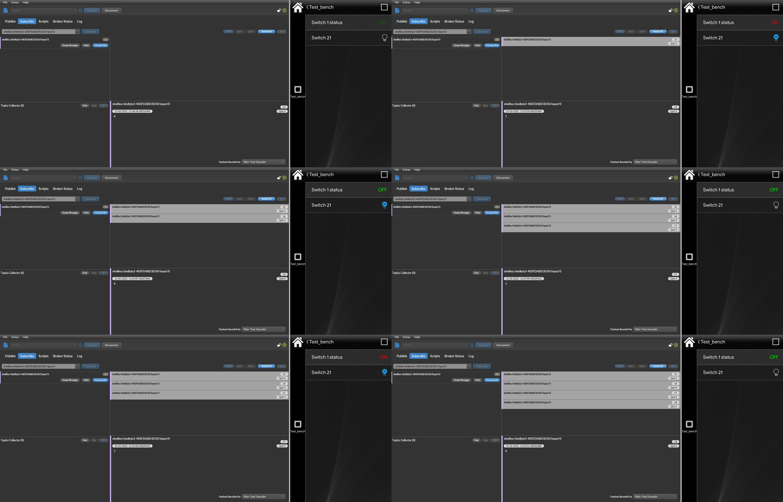
Below is shown how the component is displayed in the Ilevia Control app. As you can see in the image, when the switch is pressed the Shelly i3 device sends an MQTT message to the topic; the message contains the current value of the switch, which is shown in the status of the Text info component in the user interface.
How to configure a KNX switch to work with the Shelly i3 device
This section explains how to make the Shelly i3 device interact with a KNX switch.
Step 1.1:
Create a new KNX gateway in the Gateway section of Ilevia Manager.
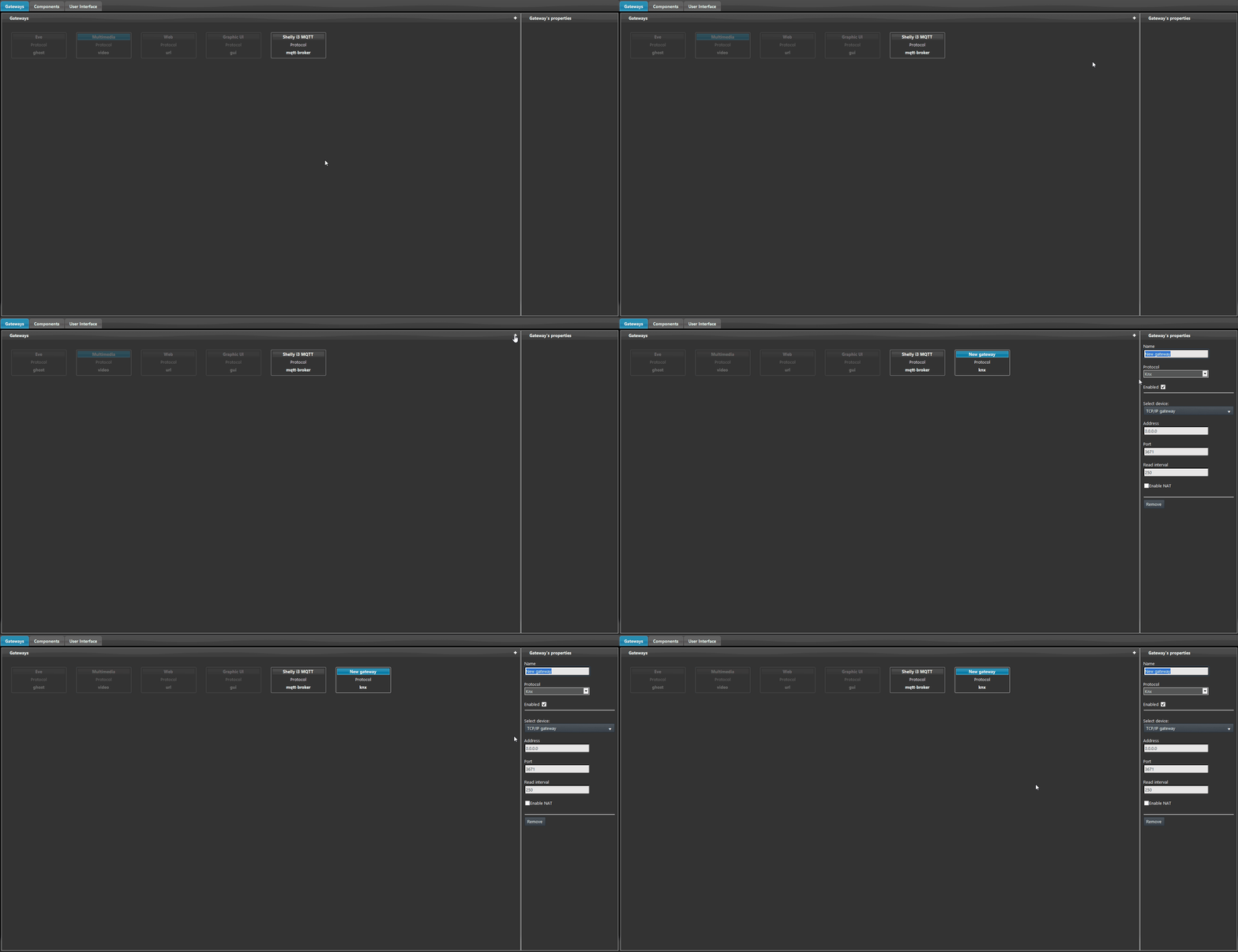
Step 1.2:
Add a new Switch component to the project and set the gateway to the KNX gateway created previously. Then enter the feedback address.
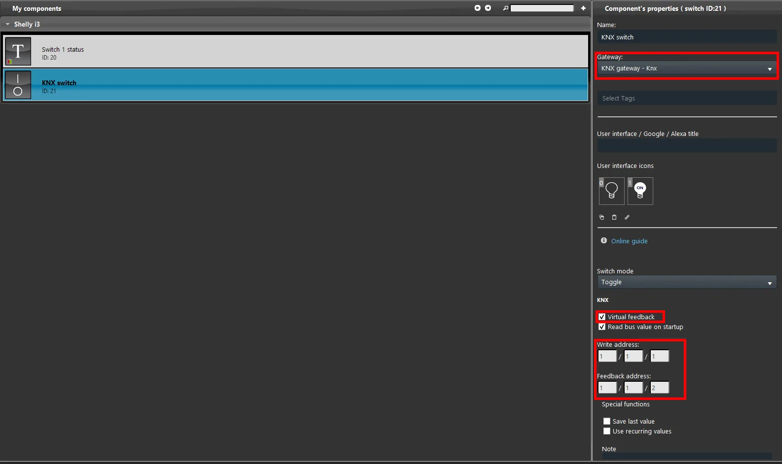
Step 1.3:
To assign a status and update it every time the wall switch is pressed, you need to set 2 logical operations in the Logic module.
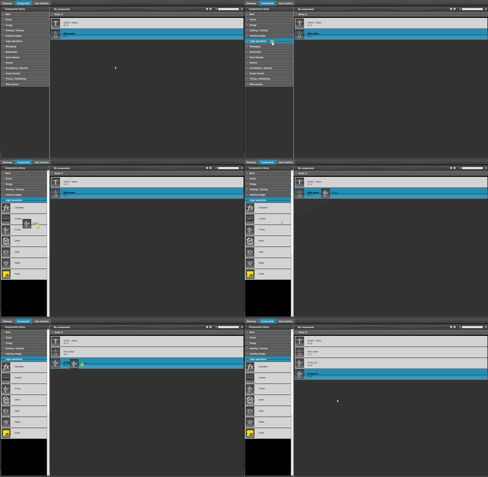
Step 1.4:
Now set the If then logics: these are used to update the statuses based on changes to one of the two components. The logics must be configured as follows:
IF THEN #1
This logic function reads the state of the switch 1 status component: IF the status value is equal to 0, the function changes the value of KNX switch; Else the KNX switch component is set to value 1.
Primary condition: set as the trigger component the one that receives the status from the Shelly i3 device, in this case the text info, by selecting it from the “Component” list; select equal to as the condition and enter value 1.
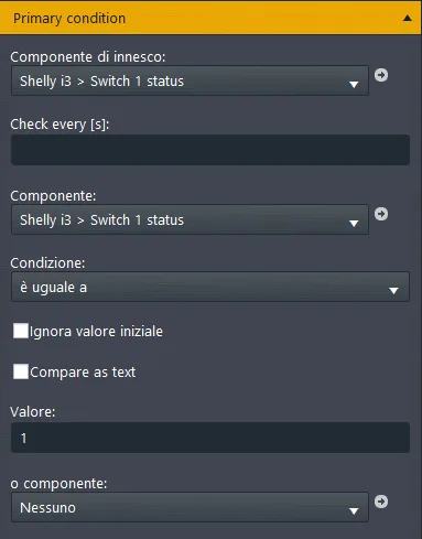
Then: select as Component the switch set with the KNX gateway; it will set the KNX switch component to value 0 every time the Shelly device status changes to that state.
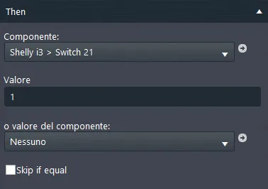
Else: select the KNX switch component as Component; it will take effect if the primary condition is false.
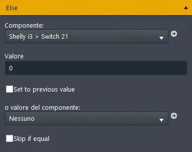
IF THEN #2
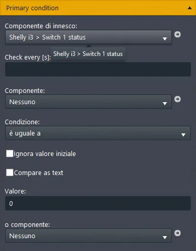
This logic function reads the state of the Switch 1 status component: if the value is equal to 0 it changes the value of the KNX switch component, otherwise the component is set to value 1.
Primary condition: set Switch 1 Status as the trigger component, which receives the status from the Shelly i3 device (in our case the Text info component), by selecting it from the “Component” list. Finally, select “Equal to” as the condition.
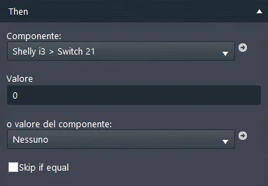
Then: in the “Component” list, make sure the component assigned to the KNX gateway is selected, then enter value 1: the KNX switch component will be set to 1.
Else: select the KNX switch component in the “Component” list; it will take effect depending on the result of the primary condition, if the entered value is not equal to 1.
Visual result in the user interface
Below is shown the visual result of configuring the two logic operations.
When you change the state of the switch (KNX switch) to On and Off, its state also changes at the same time.
Troubleshooting
1. Make sure you have the latest available version of Ilevia Manager and the X1 server firmware.
2. Make sure the Shelly device is correctly connected to your network.
3. If you cannot connect to the broker, check that your X1 has been set up correctly.