RGB Light
Properties of the RGB Light component in Ilevia Manager and how it is represented in the Ilevia Control app.
INTRODUCTION
The RGB Light component allows you to control an RGB light.
USE CASES
This component allows you to control all types of RGB lights and configure them with different gateways.
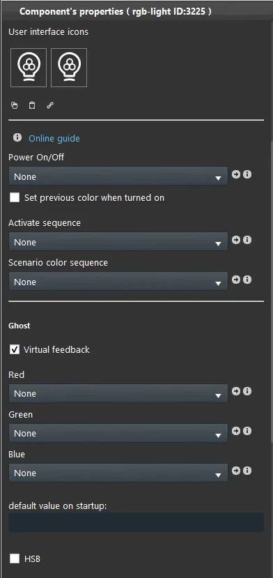
COMPONENT PROPERTIES
The component title and icon are fully editable. We recommend consulting the "Common properties" guide.
On / Off component: switch component to turn the RGB light on or off;
Activate sequence: add a Switch, Lock, Colored Info or Text Info component to activate the Color sequence scenario.
HSB: if enabled, it changes the behavior of the RGB component slider: dragging it to the right lightens the color, dragging it to the left makes it darker.
GHOST
Virtual feedback: The component will not require feedback from a physical device.
Red: Connect a Slider component to set the Red channel percentage;
Green: Connect a Slider component to set the Green channel percentage;
Blue: Connect a Slider component to set the Blue channel percentage;
Default value at startup: In this text field you can set a default value that is applied every time the server starts.
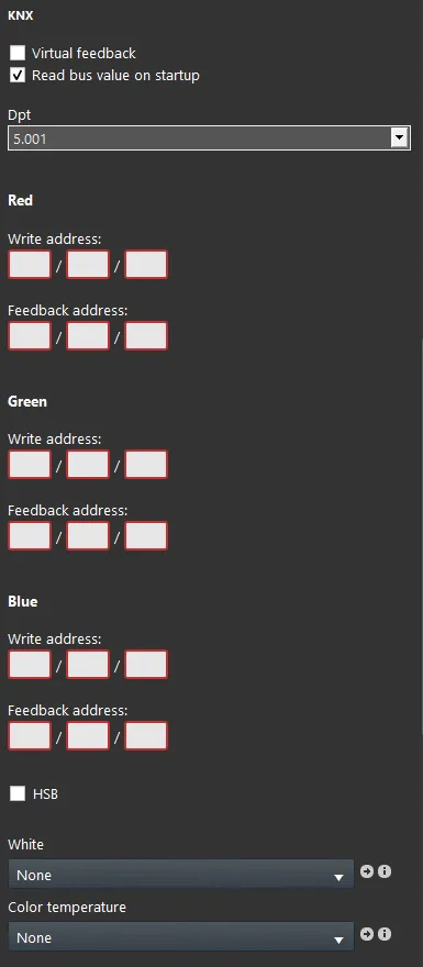
KNX
This component is built using the KNX gateway.
You can refer to the chapter "Gateway / Protocols" for more information.
Virtual feedback: refer to the chapter "KNX Protocol";
Read bus value on startup: refer to the chapter "KNX Protocol";
DPT: select the DPT between 5.001 and 232.600.
Red or RGB: enter the write and read group addresses for controlling the Red channel. If you use DPT 232.600, enter the addresses only in the first text fields (Write/Read address).
Green: Enter here the addresses related to controlling the Green channel;
Blue: Enter here the addresses related to controlling the Blue channel;
Three display modes are available: "CLASSIC", "MODAL" and "HIDDEN". For more information, see the "Common properties" guide.
CLASSIC DISPLAY
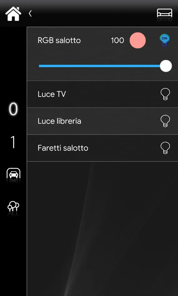
This is one of the possible results of the RGB Light component in the Ilevia Control app (classic style).
RGB lights are shown with the following masks:
RGB Light ⇒ RGB light icon

Light off = Empty icon (Editable icon, Figure 1)

Light on = Filled icon (Editable icon, Figure 2)
Color

Brightness
Figure 1
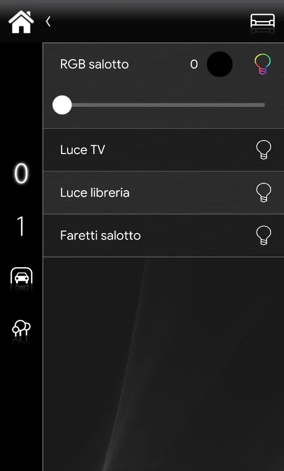
Figure 2
MAP DISPLAY
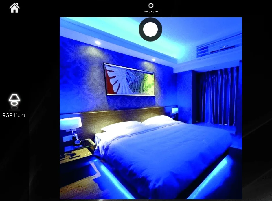
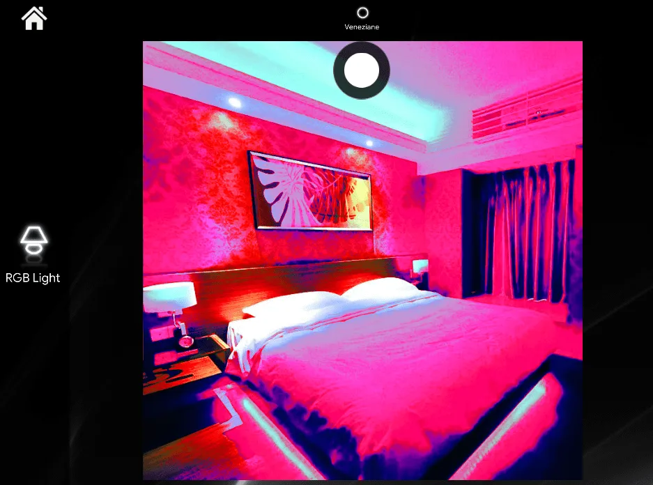
This is just one of the possible results of the component in Ilevia Control (map style).
The icons can be customized as needed, from the symbol to the color and size.
In this case, we see the default icon:
RGB Light ⇒ RGB light icon
Light off = Empty icon

Light on = Filled icon
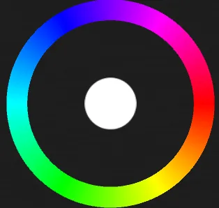
Color palette
Brightness
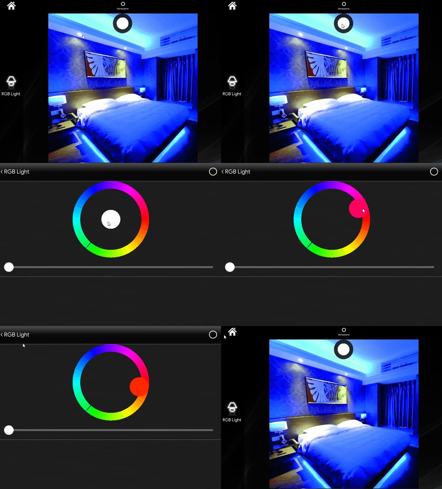
Color palette (Classic and Map)
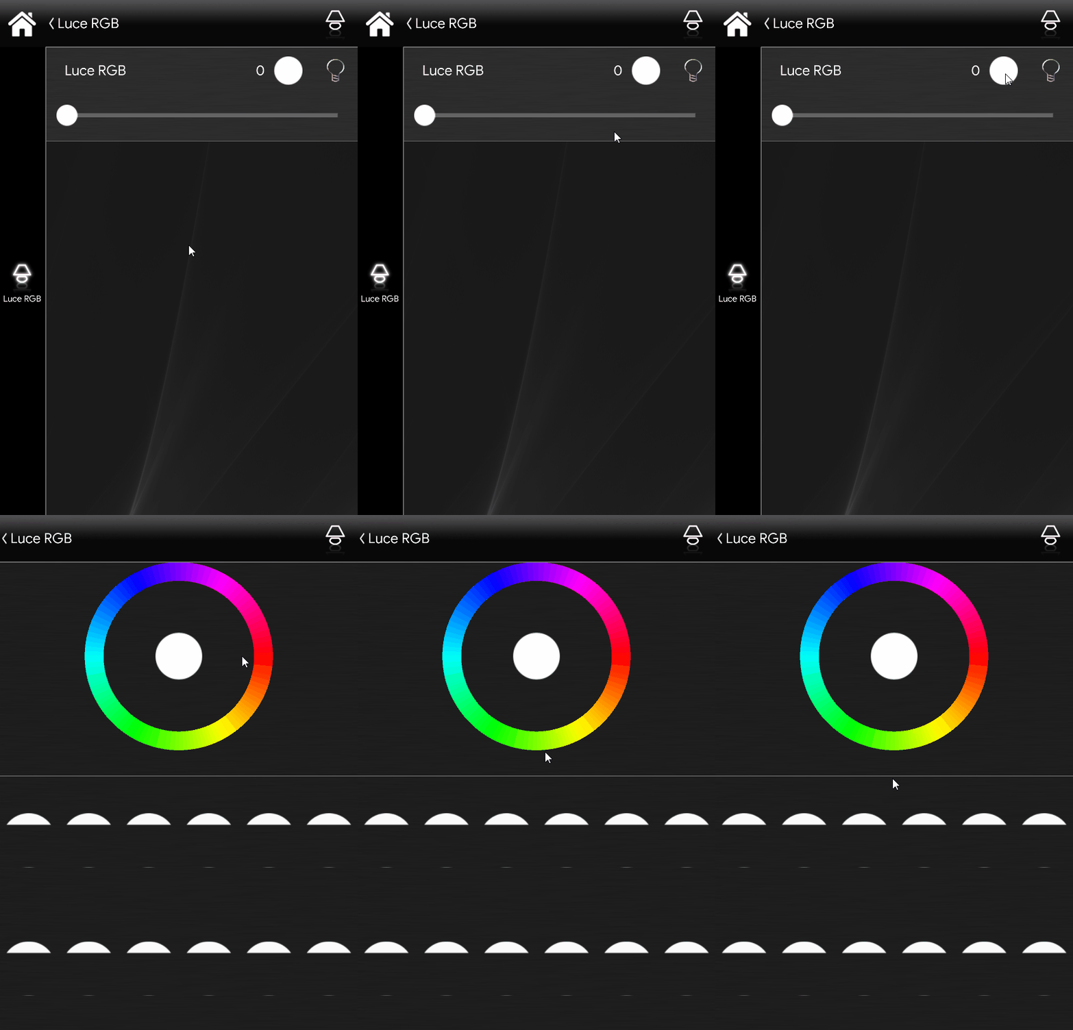
Click the icon

that shows the color currently selected in the RGB component: the colors palette will open.
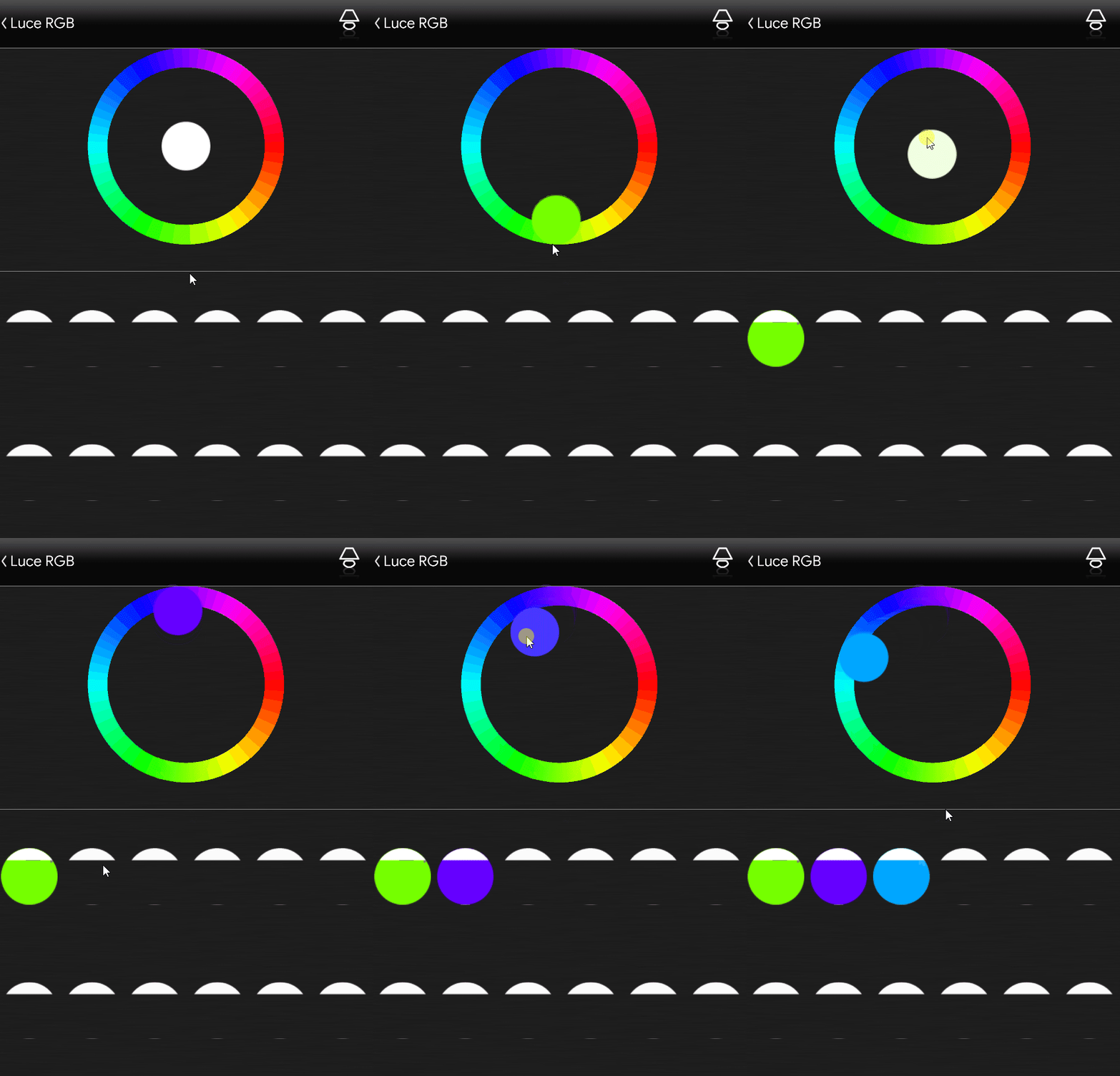
To save colors in the palette, select a color from the color picker and click one of the "Presets" until it takes on the selected color. Once saved, clicking the preset sets the RGB light to that color.
How the full Color Palette is represented within the user interface (Classic, Map)
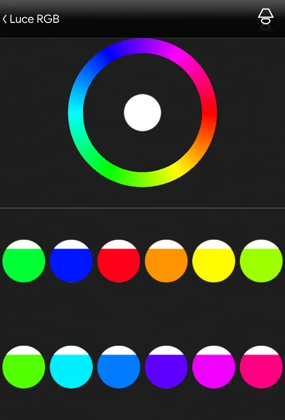
This is the visual result of the color palette in the full interface: every time you press a preset, the light linked to the component is set accordingly. You can also overwrite presets: hold down the preset to overwrite until it changes to the new selected color.
RGB light color sequence
The color sequence is a function that lets you build a scenario that defines the color sequence set on an RGB light.
Add a new scenario to the project, drag the RGB Light component into the scenario actions, and choose a color from the selector on the right. Add a delay between each color, as shown in the image below.
This operation can be repeated as many times as desired.
Step 1:
Add a new Scenario component to the Ilevia Manager project.
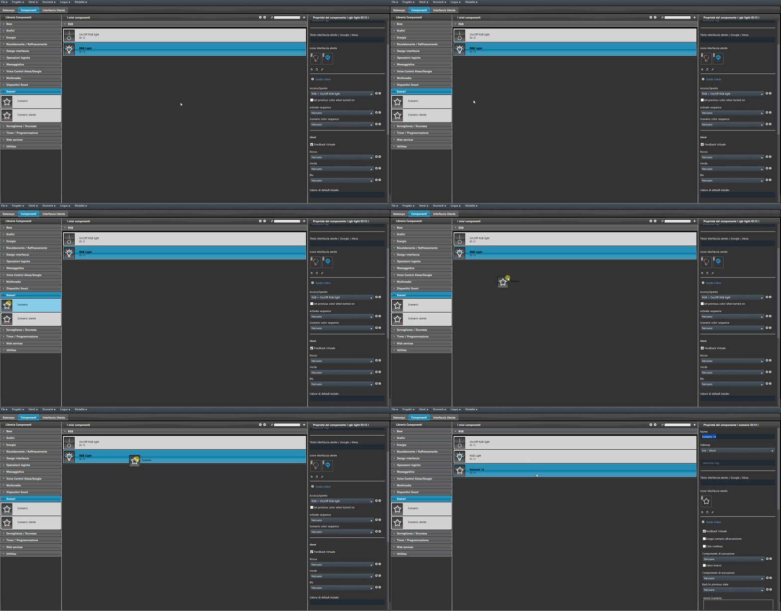
Step 2:
Drag the RGB Light component into the Scenario as shown in the image below.
This operation can be repeated as many times as desired.
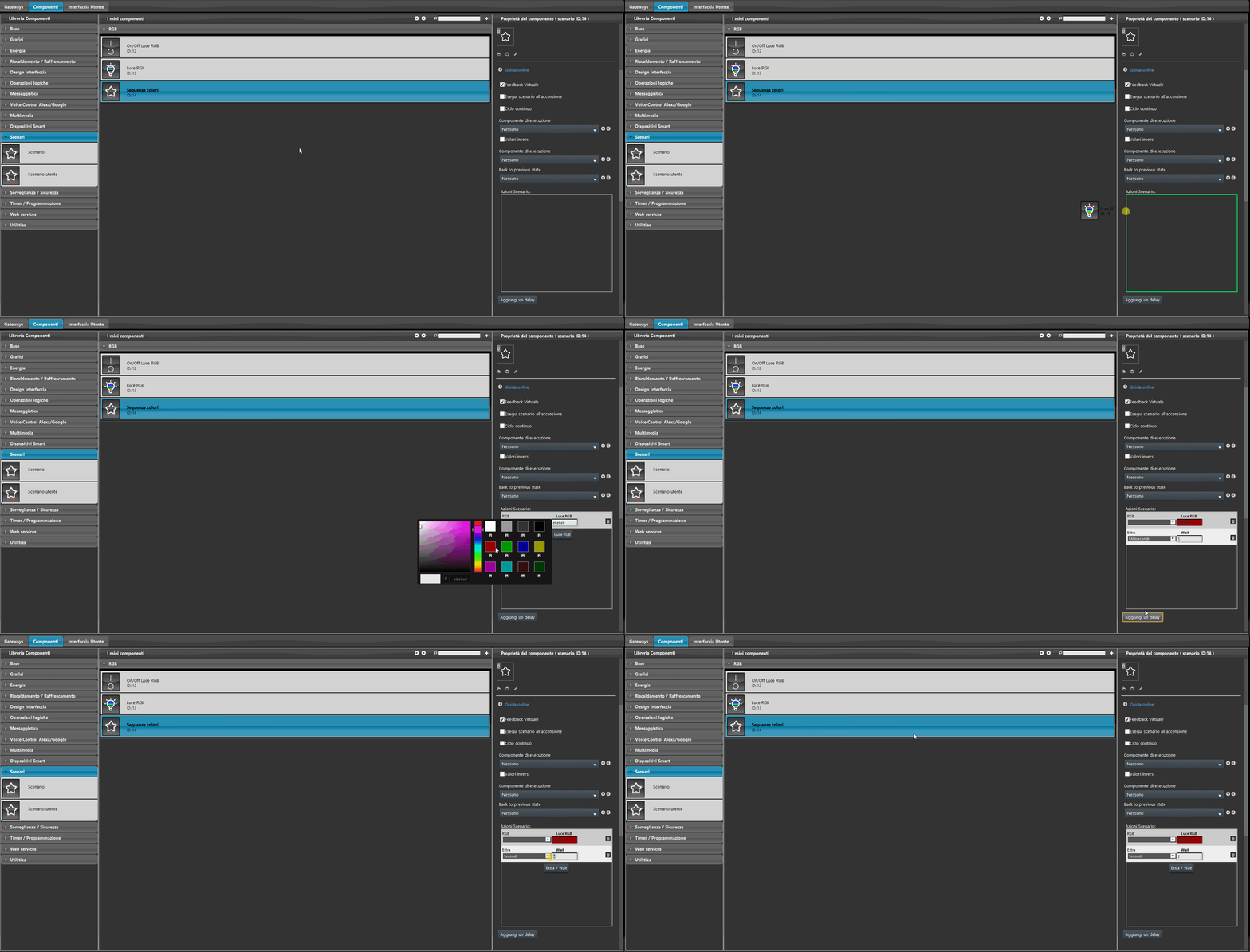
Step 3:
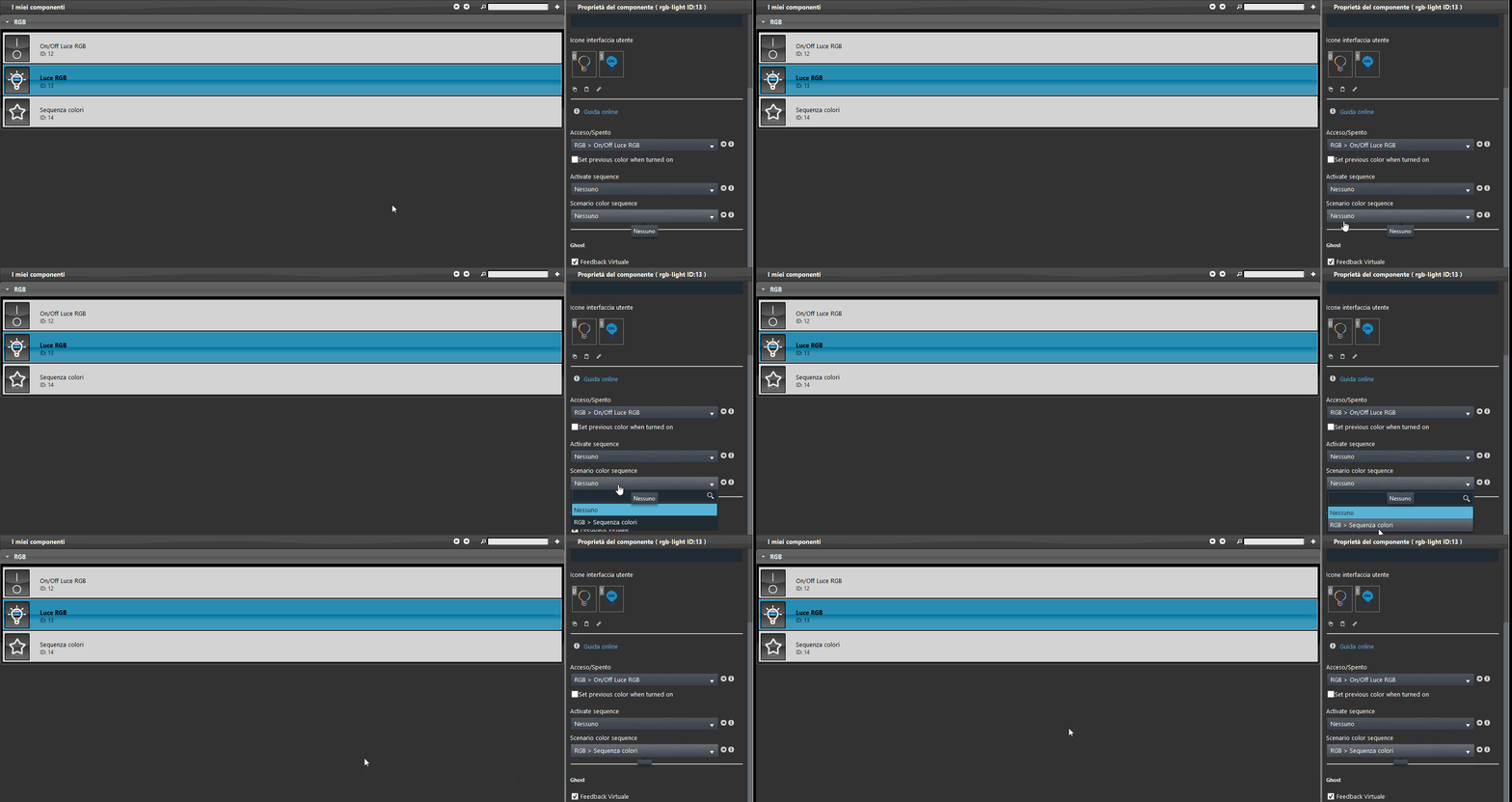
Access the properties of the RGB Light component and enter the scenario with the color sequence in the option list field dedicated to the sequence. The same scenario can be used for multiple RGB Light components.
Step 4:
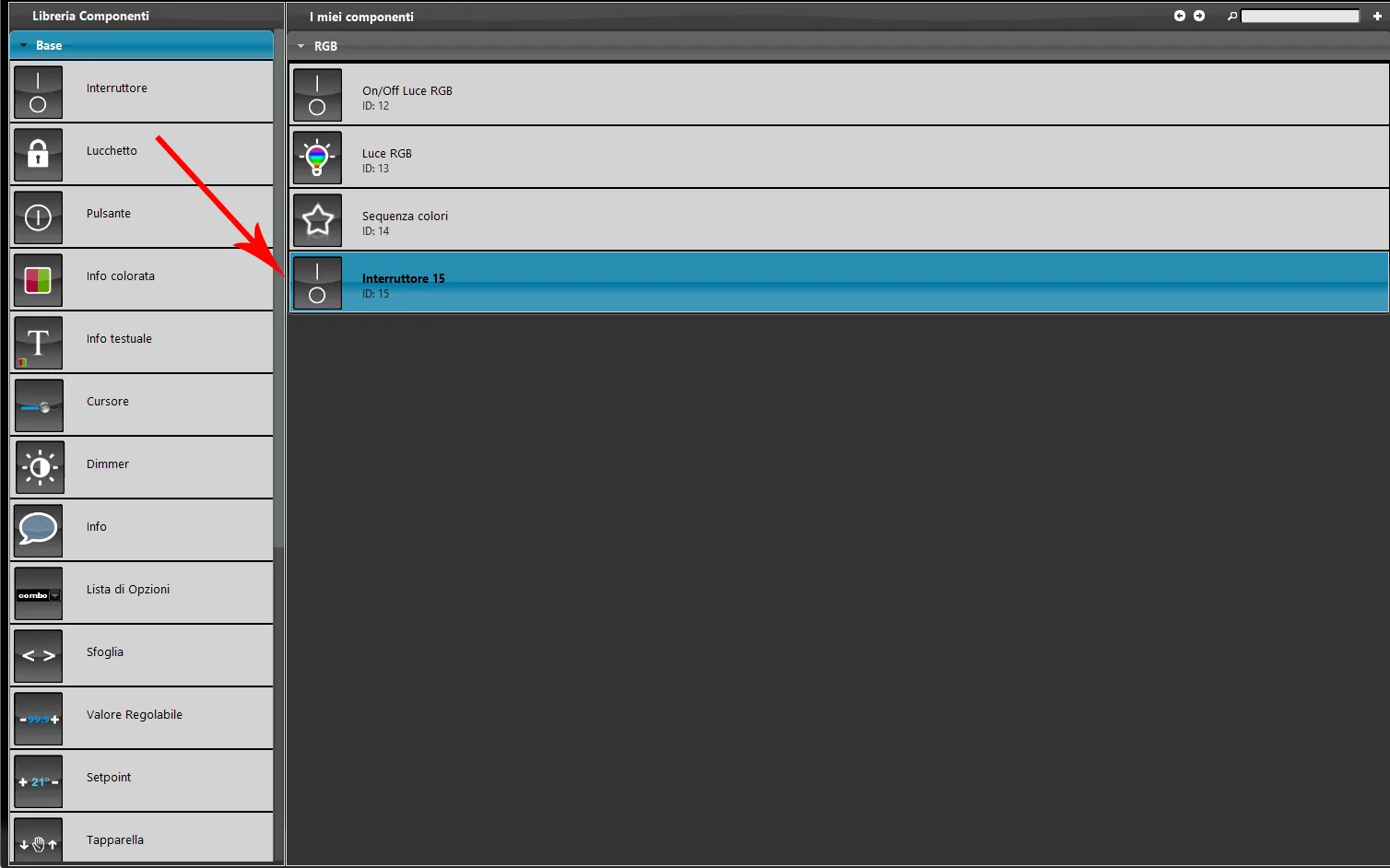
Add a new Switch component to the project by dragging it from the Component Library.
Step 5:
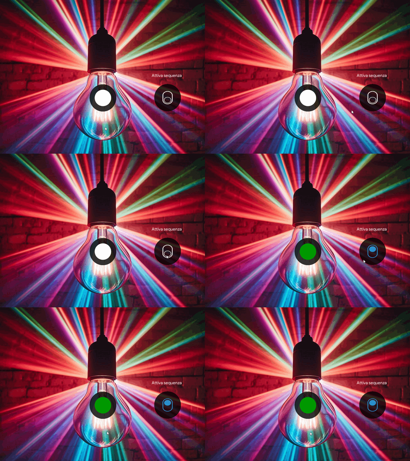
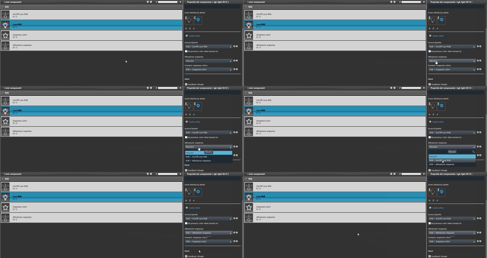
Connect the Switch component to the RGB Light component using the Activate sequence drop-down menu.
User interface view (Classic and Map)
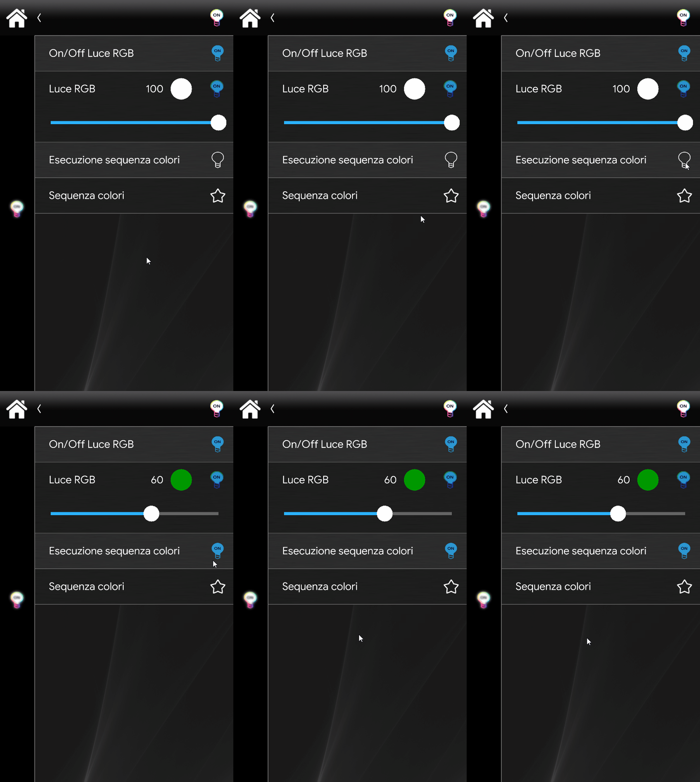
The images below show the visible result of the color sequence in both user interfaces. The sequence starts every time the RGB light is switched on and is reset every time the RGB device is switched on.
Classic User Interface
Map User Interface