Quick start: Raspberry Pi (testing only)
From installing the Ilevia server on a Raspberry Pi (for trials and testing) to your first project with Ilevia Manager and Ilevia Control.
This guide walks you step by step from installing the Ilevia server on a Raspberry Pi to creating your first project with Ilevia Manager, up to controlling the components from the Ilevia Control app.
The Raspberry Pi is meant for trials and testing; for real installations we recommend the Ilevia X1 Plus server.
Server installation
Network configurations
When you connect for the first time, connect the LAN network adapter to the network, then connect the power cable. The Server will boot from the inserted card (the Micro SD of the Raspberry Pi), which stores all firmware and user data. The Server will now automatically obtain the IP address from the router (DHCP server). It is important that the Server is connected to the same network as the computer so that you can use the Server Connection command within Ilevia Manager.
Server connection: local connection
Open Ilevia Manager (downloadable from the download page). Go to the “Project” menu, then select the “Connect” command. The Connection window will appear. Now select the “Search” button to search for all servers on the network. The Server will appear in the Search results list with its name, IP address, and License ID.
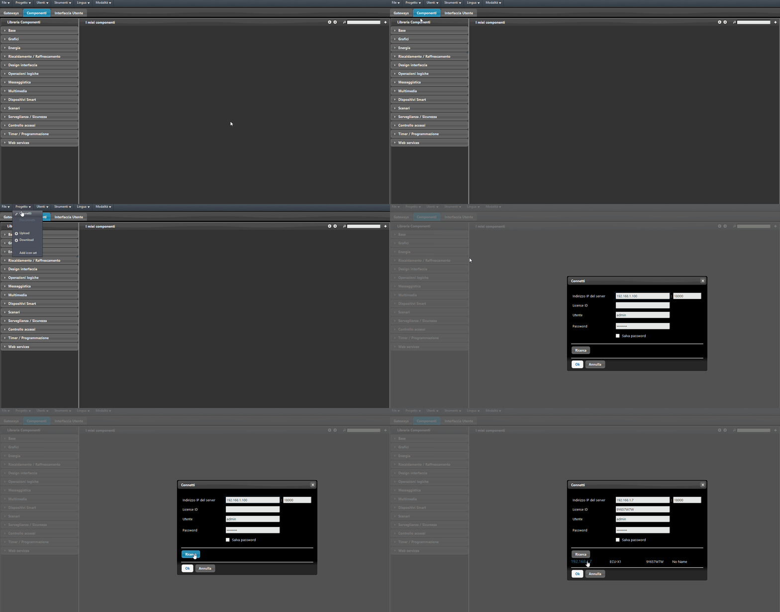
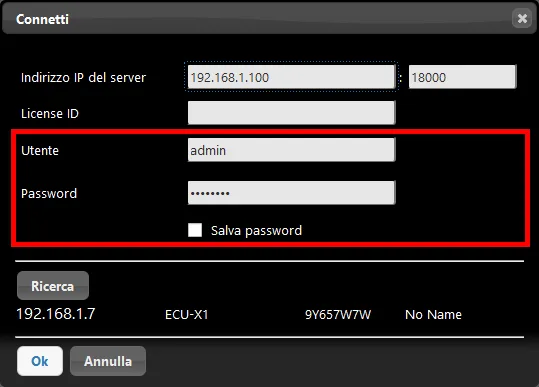
Select the Server shown in the search results to continue. Enter username and password (default credentials: “admin” and “password”, to be changed after the first configuration) and finally select the OK command to connect.
Server connection: direct connection
If no router is available in the installation or if you want to program the Server quickly, you can connect directly through the PC.
! Manual IP address setup
If there is no DHCP server or router assigning an IP address to the Server, you must set one manually. By default, this should be in the 192.168.1.x range.
> How to change network settings (disable DHCP and use a static IP address)
Step 1: Network adapters
Open the Windows Control Panel and go to the Network and Sharing Center. Click Change adapter settings on the left side of the screen.
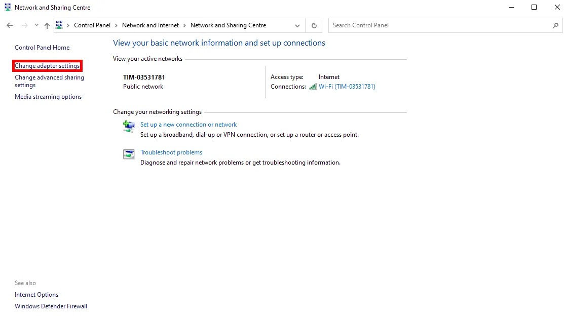
Step 2: Adapter properties
Right-click the Ethernet adapter (the one connected to the Server); the adapter properties window will open.
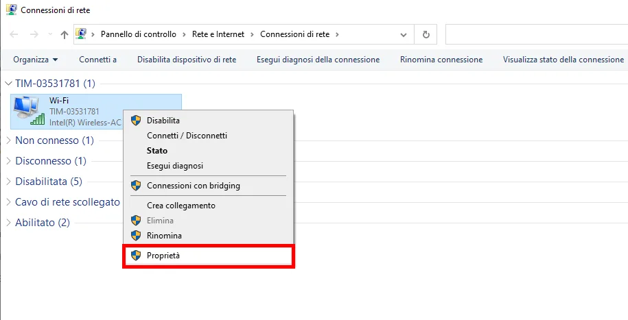
Step 3: IPv4
Scroll down the list until you find “Internet Protocol Version 4 (TCP/IPv4)” and click the Properties button to change the adapter's IPv4 properties.
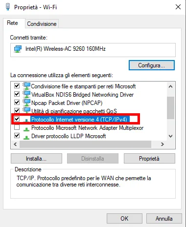
Step 4: IPv4 properties
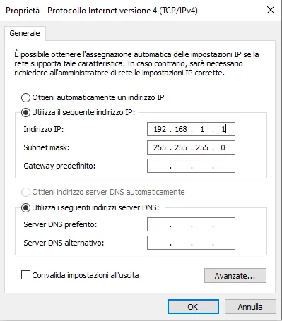
Here you can assign a static IP address to the computer. Click the “Use the following IP address:” option and enter the IP address and subnet mask. The computer's IP address must be different from the one used by the Server. By default, if there is no router, the Server IP address is 192.168.1.100: set the computer to a different address, for example 192.168.1.1 (simulating a router).
Press Enter after entering the IP address: the subnet mask will be filled in automatically with 255.255.255.0. That is fine: click OK and close the Control Panel network adapters window.
Firmware update
From time to time, new firmware updates are released; install them by following the procedure below.
Administrator panel
Turn on the server and connect it to your LAN network;
Open your web browser;
Copy the link and paste it into the search bar http://www.ilevia.com/evelocalip.php.
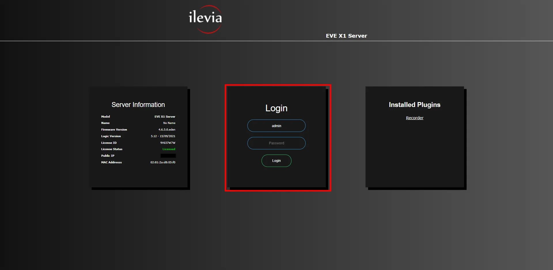
The browser will display a list of all available Ilevia server IP addresses on the local network. If there is only one Ilevia server on the local network, you will be automatically redirected to its web interface (as shown in the figure below).
Within the web interface you will find:
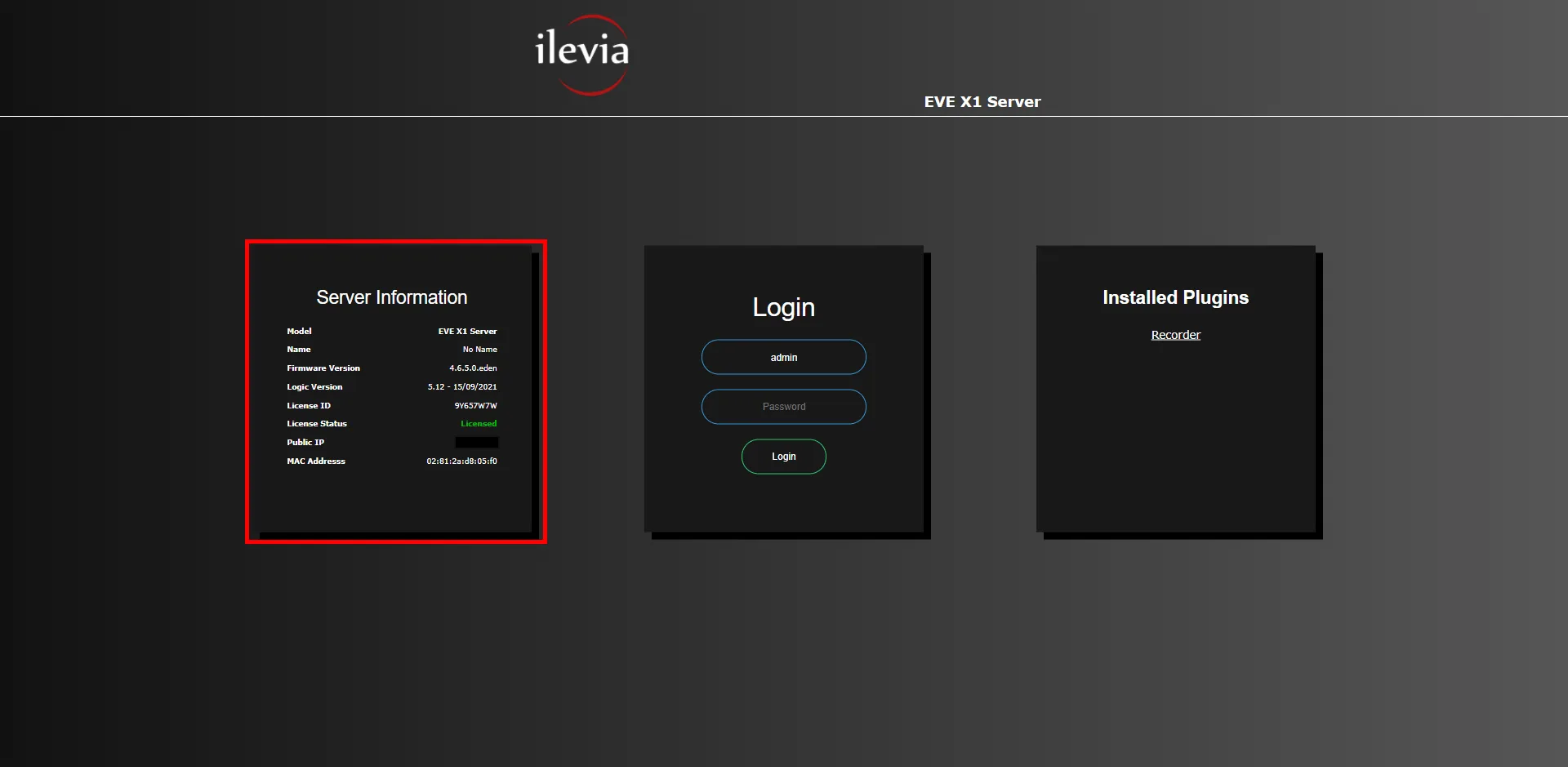
Log in with your username and password (the default credentials are ‘admin’ and ‘password’). Once logged in, the navigation menu will be displayed.
Utility Menu
Open the Utility section from the main menu;
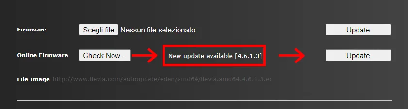
Click Check now (Check now) to check for available firmware updates;
If a new firmware version is available, click Update (Update);
Wait for the system to restart, then you will be able to log in.
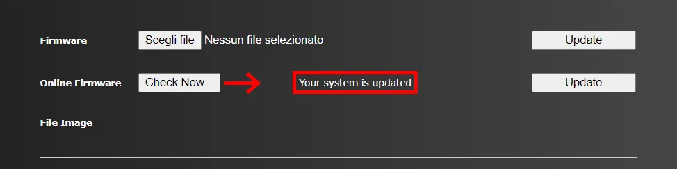
If the system is already updated to the latest firmware version, a message is displayed.
The complete procedure is in the Firmware update guide.
We will start by creating a project from scratch using the Ilevia Manager configuration software.
We will start by creating a project from scratch using the Ilevia Manager configuration software.
In the initial section, you will see how to configure a switch component and how to set up a simple user interface.
Finally, it will be explained how to upload an Ilevia project to the server and control the components in it from the Ilevia Control app.
1.1 Gateway creation
The Gateway section is made up of two different areas: Gateway and Gateway properties.
There are 4 preconfigured gateways, created by default and not removable.
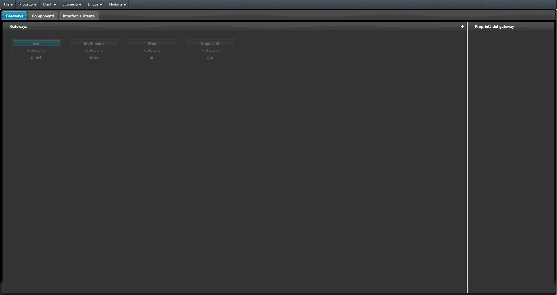
Now we will create a new gateway to connect the Ilevia server to the KNX bus.
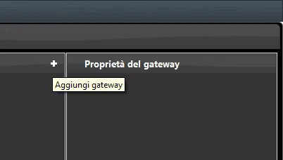
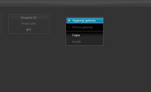
Click the “+” icon in the upper-right corner within the Gateway section, or right-click and select add gateway. A new gateway will be created.
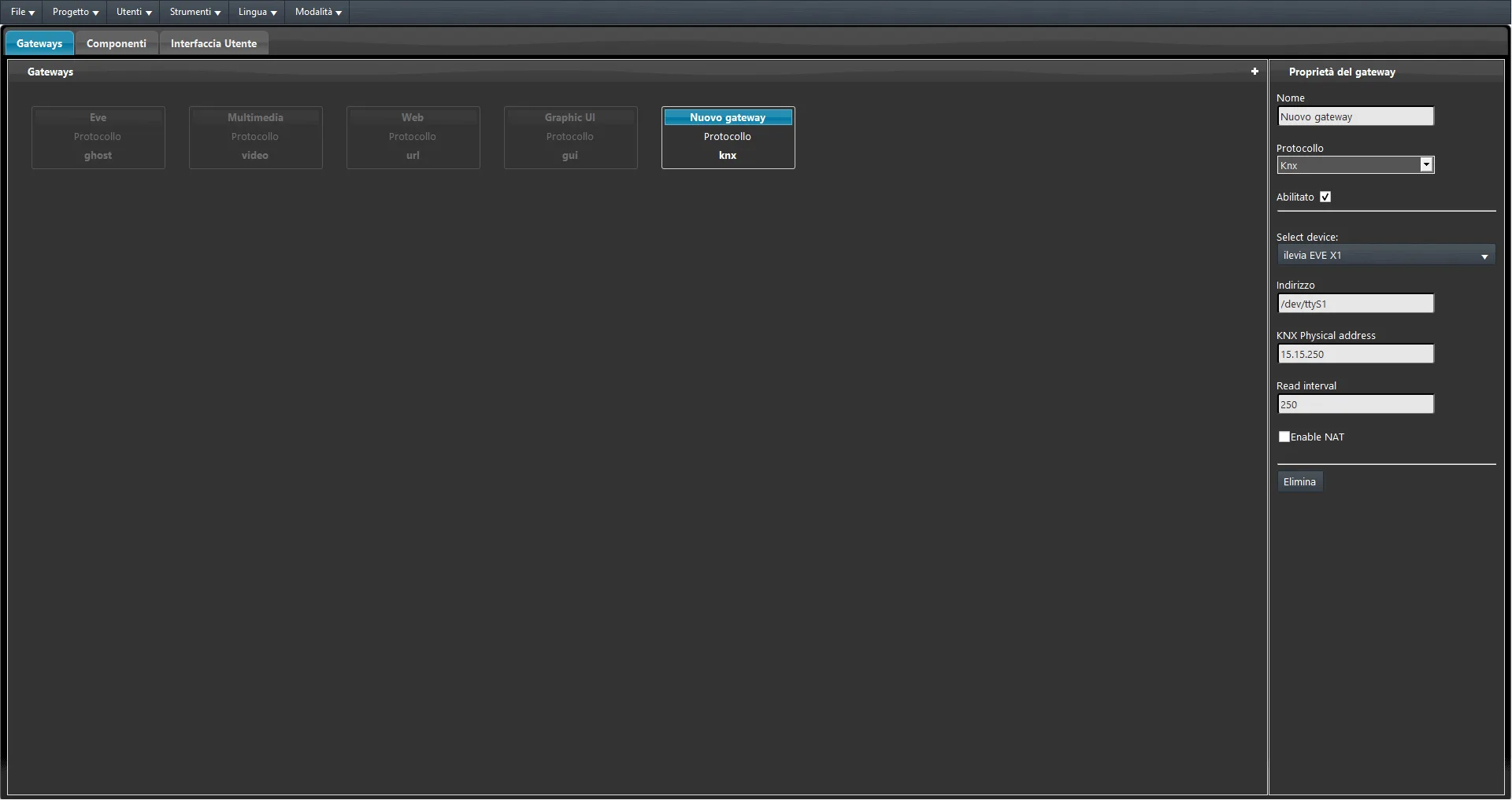
Set a title and select the KNX protocol from the protocol menu in the gateway properties.
If you have set the protocol to KNX/IP mode, enter the IP address of the KNX IP interface.
Change the port according to your configuration.
1.2 Component configuration
The Components section is made up of three different areas: Component library, My components, and Component properties.
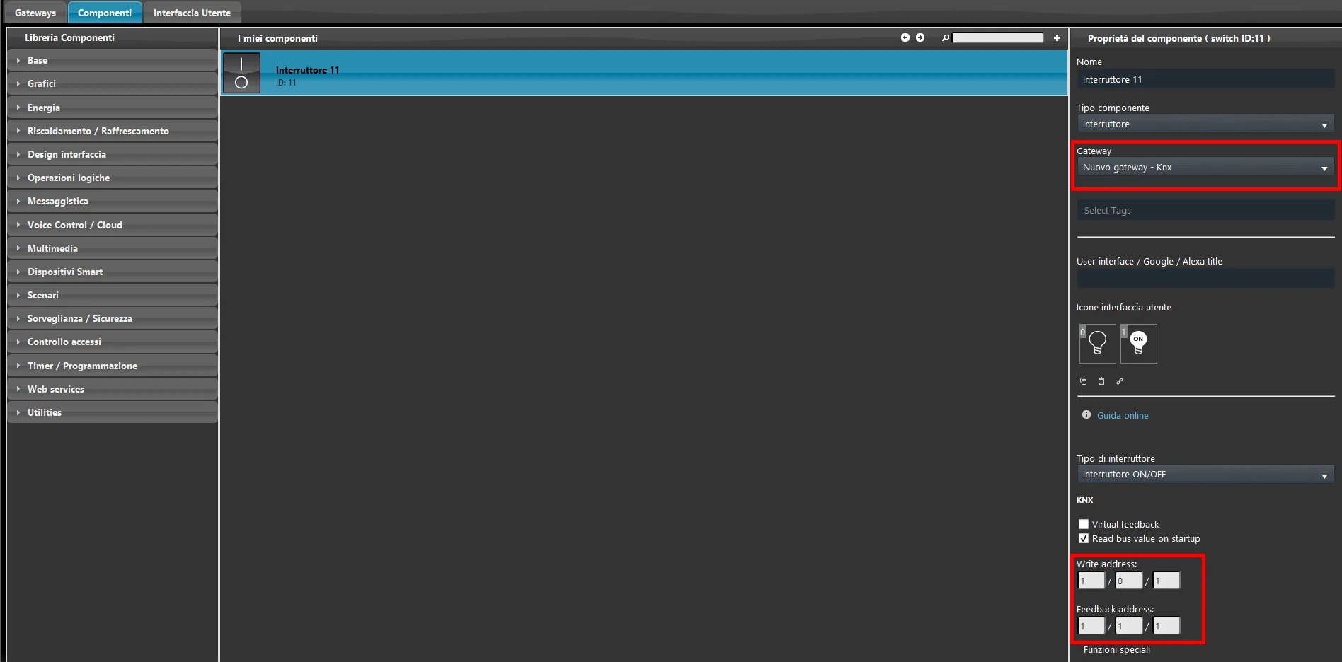
Drag a “SWITCH” component from the component library to the My components section.
Complete the Write and Feedback address fields in the component properties.
The Write and Feedback address correspond to the actuator connected to the KNX bus line.
1.3 Upload to the server
Save the project, then select Project in the menu bar and then Upload to the server.
The project upload window to the server will open. Make sure to enter the correct data.
Select Search and then the IP address of your Ilevia server.
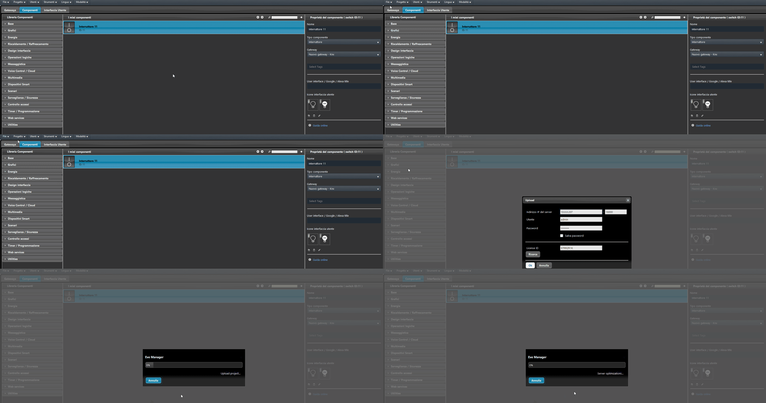
Enter “admin” as the username and “password” as the project password (default credentials).
Select Ok and the current project will be uploaded to the Ilevia server.
1.4 Real-time connection
Select Project from the top menu and then Connect.
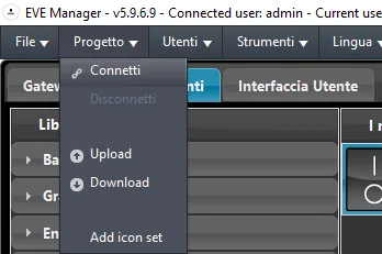
The connection window will appear. Make sure to enter the correct connection data.
Select Search and then the IP address of your Ilevia server.
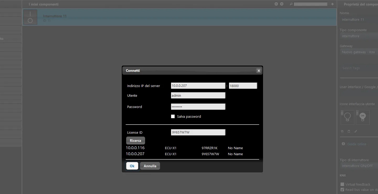
Enter “admin” as the username and “password” as the project password (default credentials).
Select Ok and Ilevia Manager will connect to the Ilevia server.
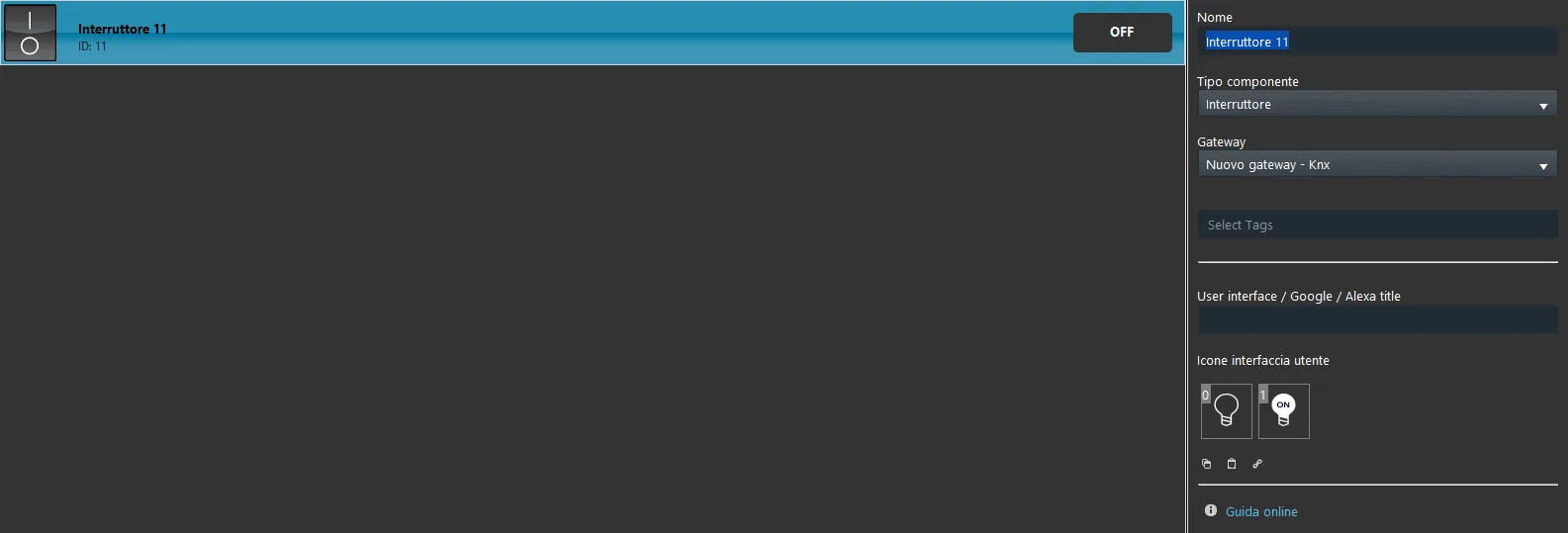
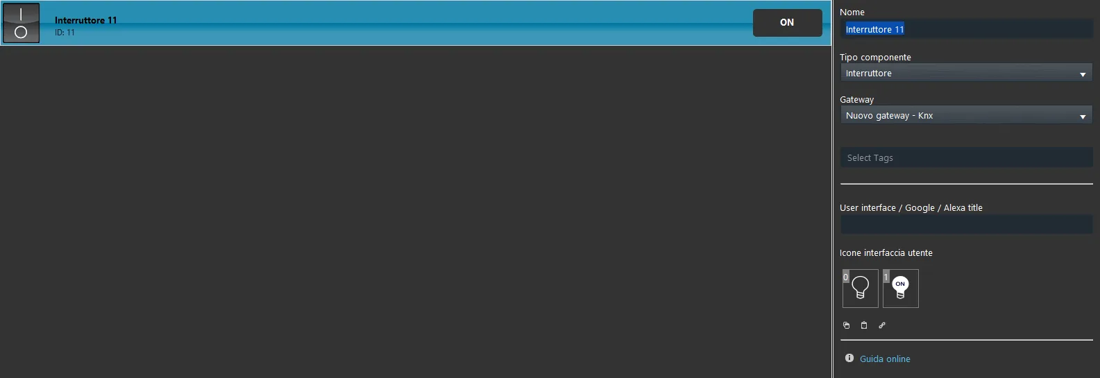
Once connected, it will be possible to monitor the component status in real time.
If the configuration is incorrect, the status panel for the component will display “N.D.” (not defined).
1.5 User interface creation
NOTE
Ilevia allows you to configure 2 user interface styles (Classic and Maps), with different views.
Each user has their own user interface (Classic or Maps). The Classic interface is the default mode that Ilevia Manager allows you to configure.
To control the home with both interface styles, you will need to create two different users and configure 2 different interfaces.
User interface section. This section is made up of two different areas:
1. Icons / My components (right area), which contains the icon sets and the configured components;
2. < m1>Interface grid (left area), where you will configure the user interface;
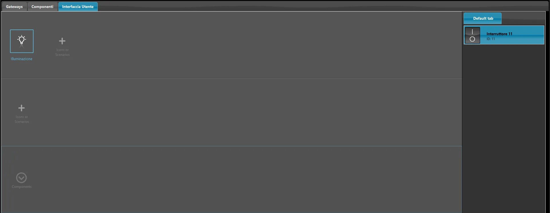
Select the Icons section, then drag an icon into the first row at the top left of the interface (Icons and scenarios level).
This is the first icon in the main menu of your new user interface.
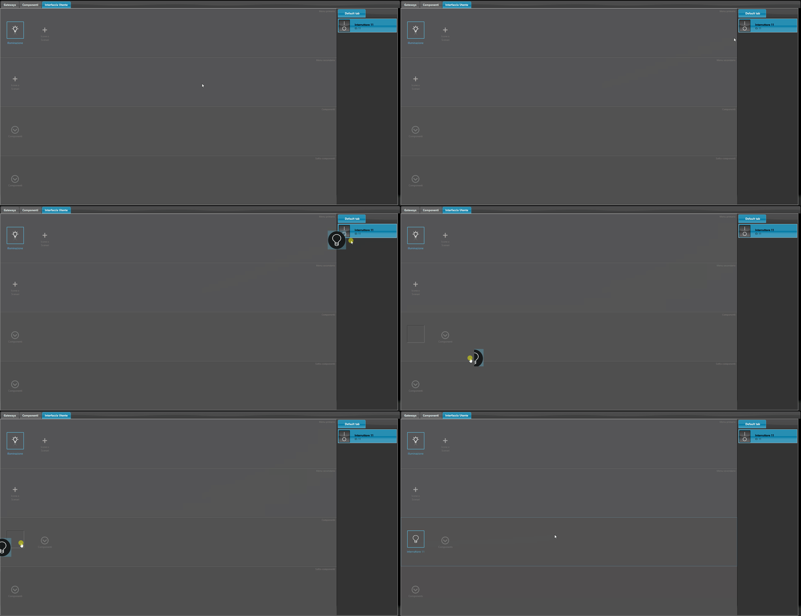
Select the My components section, then drag the component into the interface grid on the left side of the screen (Components level).
This will create the components menu containing the newly added component.
1.6 Project upload to the server
Save the project, then select the Project menu at the top of the screen and then Upload.
The upload window to the server will appear. Make sure to enter the correct credentials.
Select Search and then the IP address of your Ilevia server.
Enter “admin” as the username and “password” as the project password (default credentials).
Select Ok and the current project will be uploaded to the Ilevia server.
1.7 Access to Ilevia Control
Launch the Ilevia Control app (mobile or desktop version).
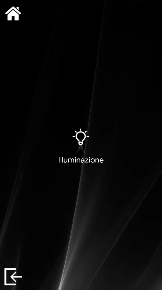
Select the “+” icon in the upper-right corner of the screen. A new account will be created (Fig. 1).
Set a title for the new account, then enter the IP address (or select it from the autosearch menu). Enter “admin” as the username and “password” as the password (default credentials), unless they have been changed in the project (Fig. 2).
Once done, return to the main screen and select the newly created account to load and display the user interface (Fig. 3).
You can edit the account settings by dragging the account icon with your finger (or mouse pointer), as shown in the image below (Fig. 4).
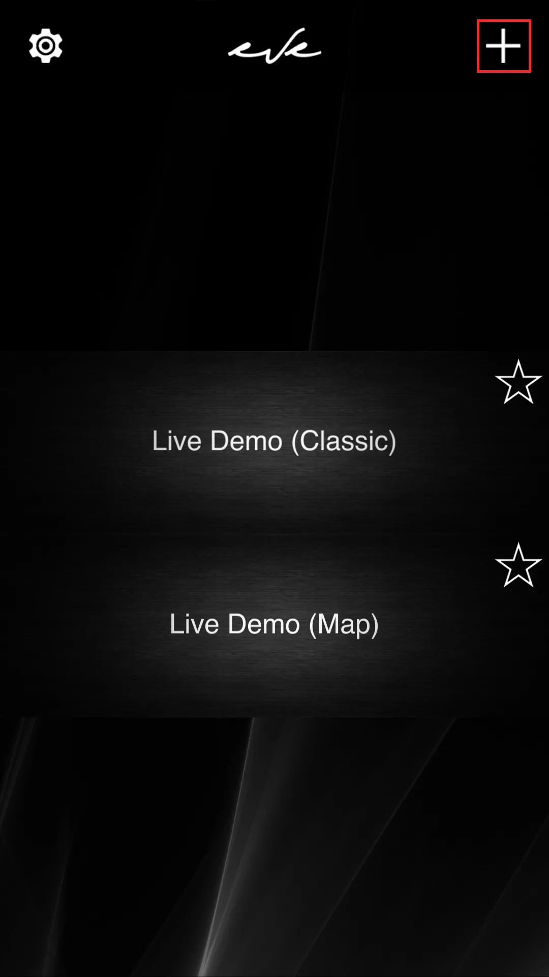
Fig. 1
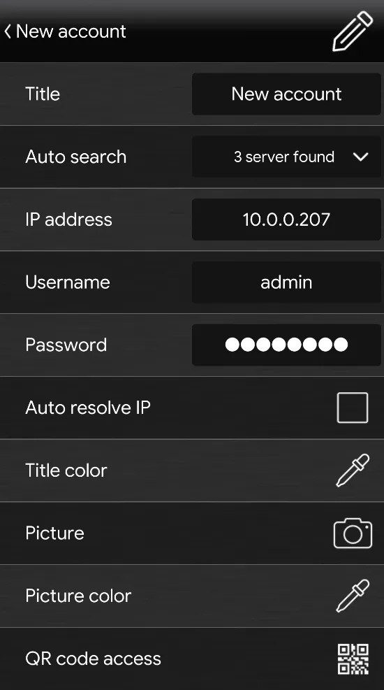
Fig. 2
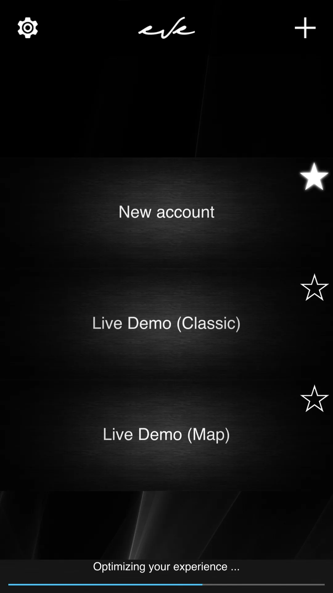
Fig. 3
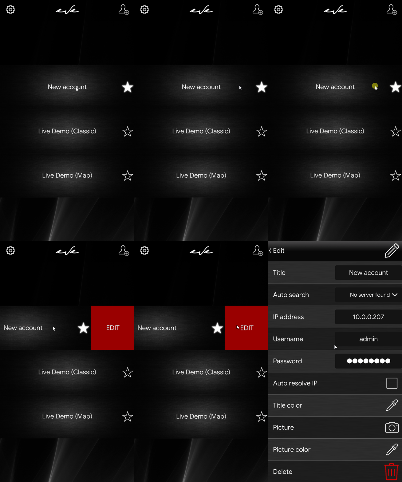
Fig. 4
1.8 Interface operation
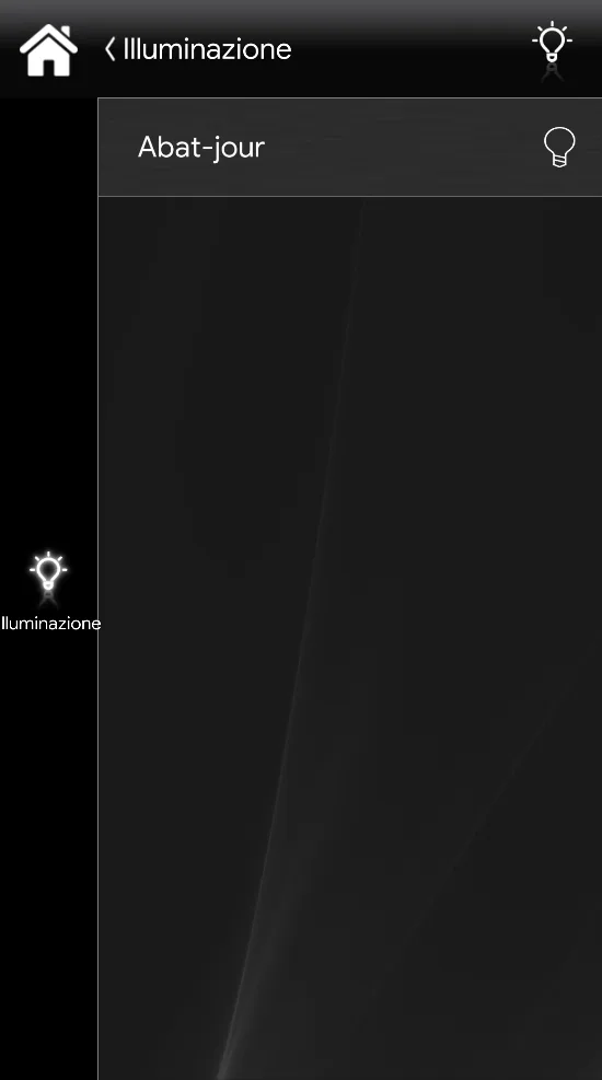
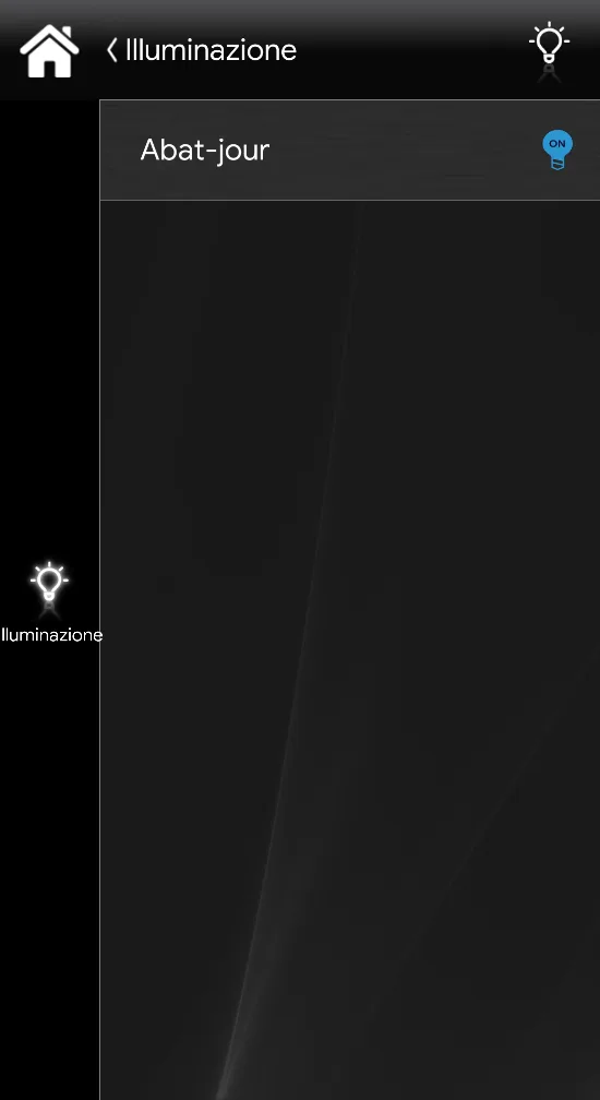
Once the user interface is loaded, this is what will be shown to the user (Classic user interface).
Click the icon to turn on or turn off the configured light.
In this part of the guide, you will be shown step by step how to configure an Ilevia project starting from the import of KNX group addresses.
In this part of the guide, you will be shown step by step how to configure an Ilevia project starting from the import of KNX group addresses.
Here you will find all the basic information you need to create your first project using the Ilevia system.
Gateway creation
We start with an empty project. Select “File” from the top menu of Ilevia Manager and click “New”.
Now we proceed with creating a new KNX gateway that connects the Ilevia server to the KNX bus.
See paragraph 1.1 “Gateway creation” in the chapter “Creating the first project”.
Component configuration
Let’s move to the Components section.
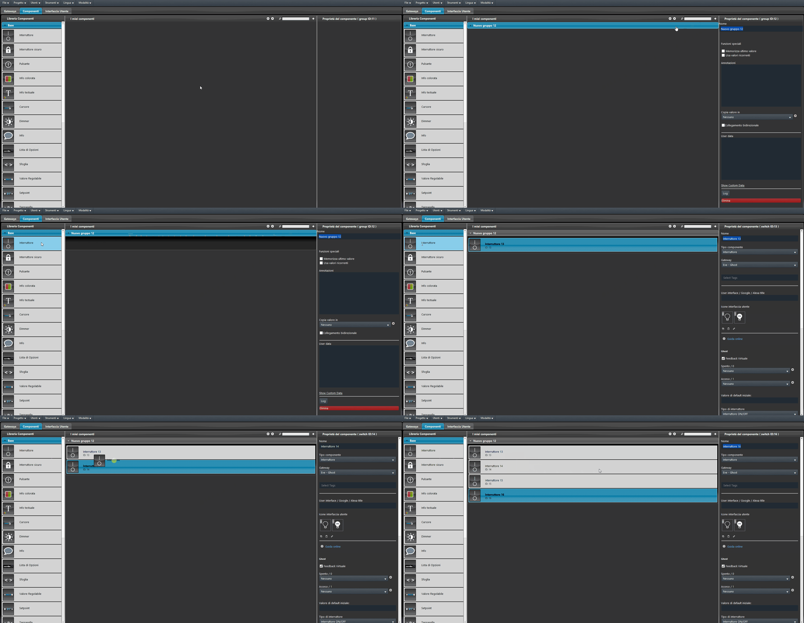
Drag all the components you need from the components library to the “My components” area.
You can also organize components into groups. Click the “+” icon in the upper-right part of the Components section.
This will create a new group, which you can rename as you wish. Finally, drag the components into it.
Step 1:
To begin, export the project from the ETS software and then import it into Ilevia Manager.
Right-click the selected project, choose Export, and save it in a folder of your choice with the extension .esf (OPC EXPORT).
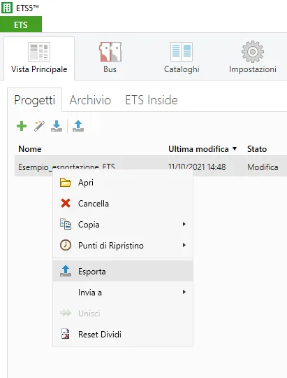
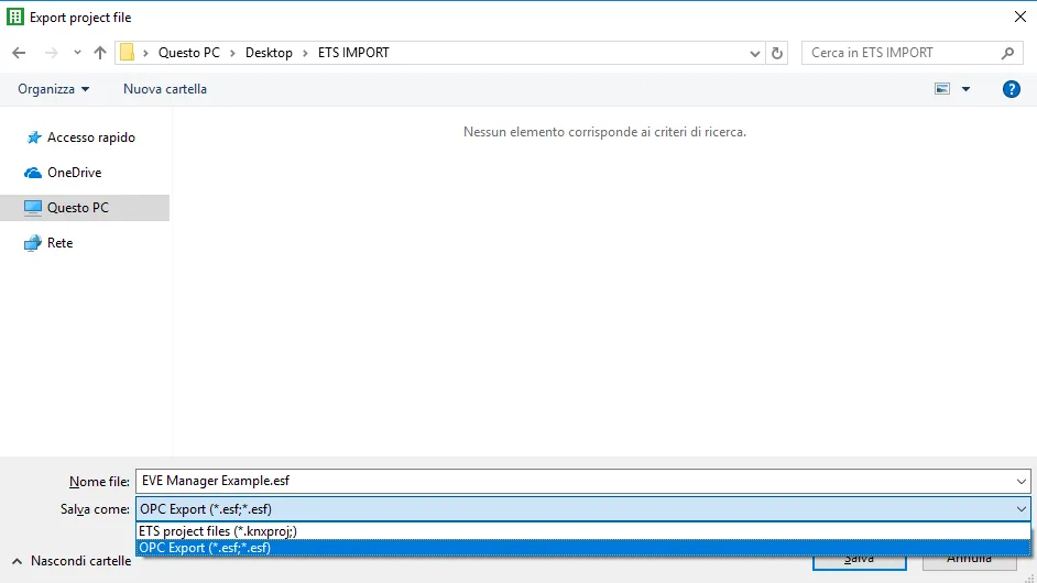
Step 2:
Move to Ilevia Manager: select the Tools menu at the top of the screen, then “Import” → “ETS Groups”.
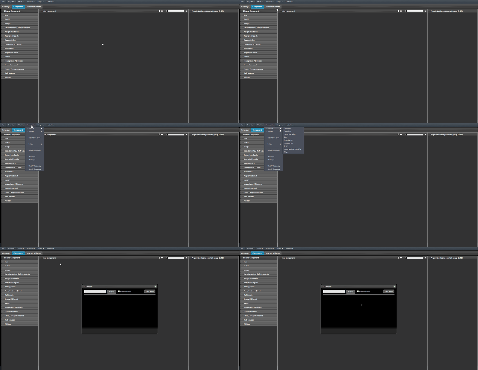
Step 3:
Load the .esf file: once you have selected the file, a tree view will be shown in a new window with the group addresses previously created in ETS.
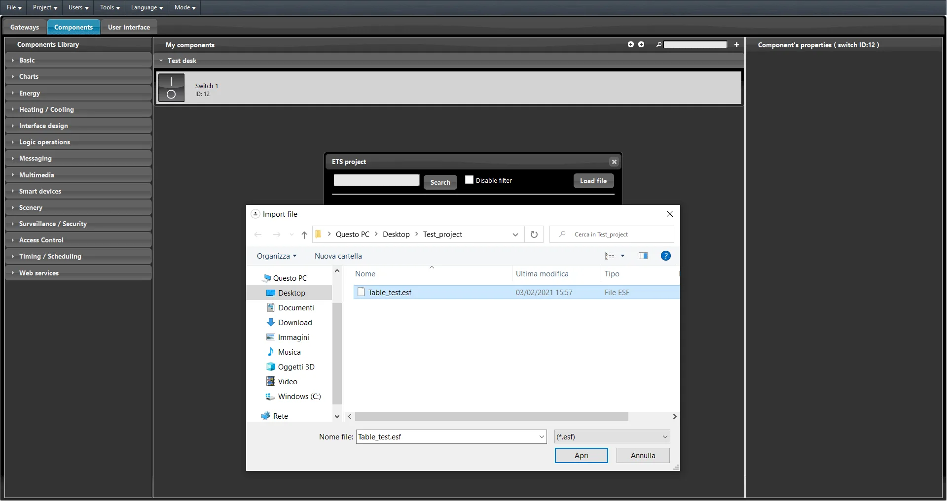
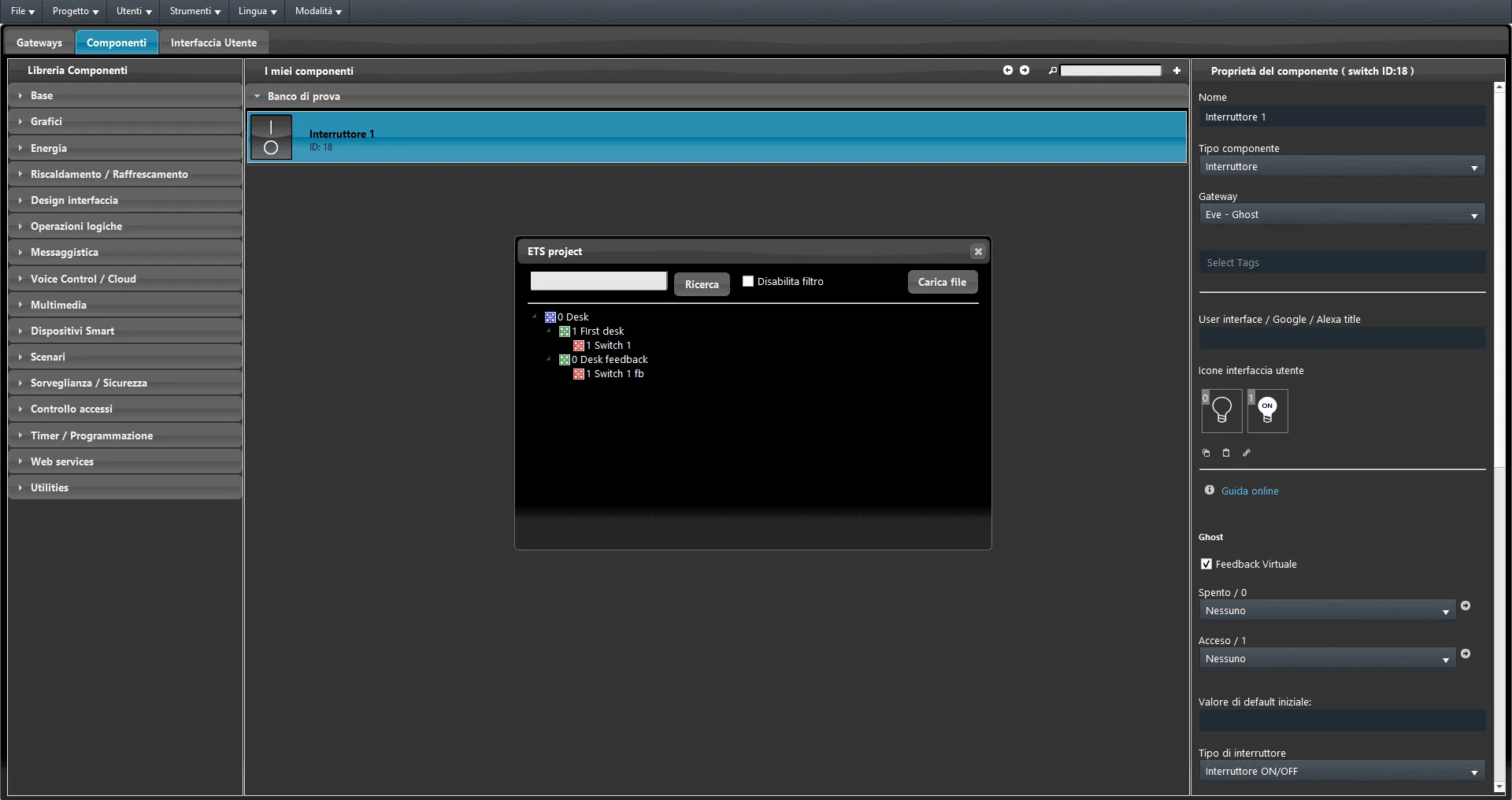
Step 4:
Select the component you want to configure from the “My components” area.
Drag from the “ETS project” window the group address you want to associate with the component, as shown in the image below.
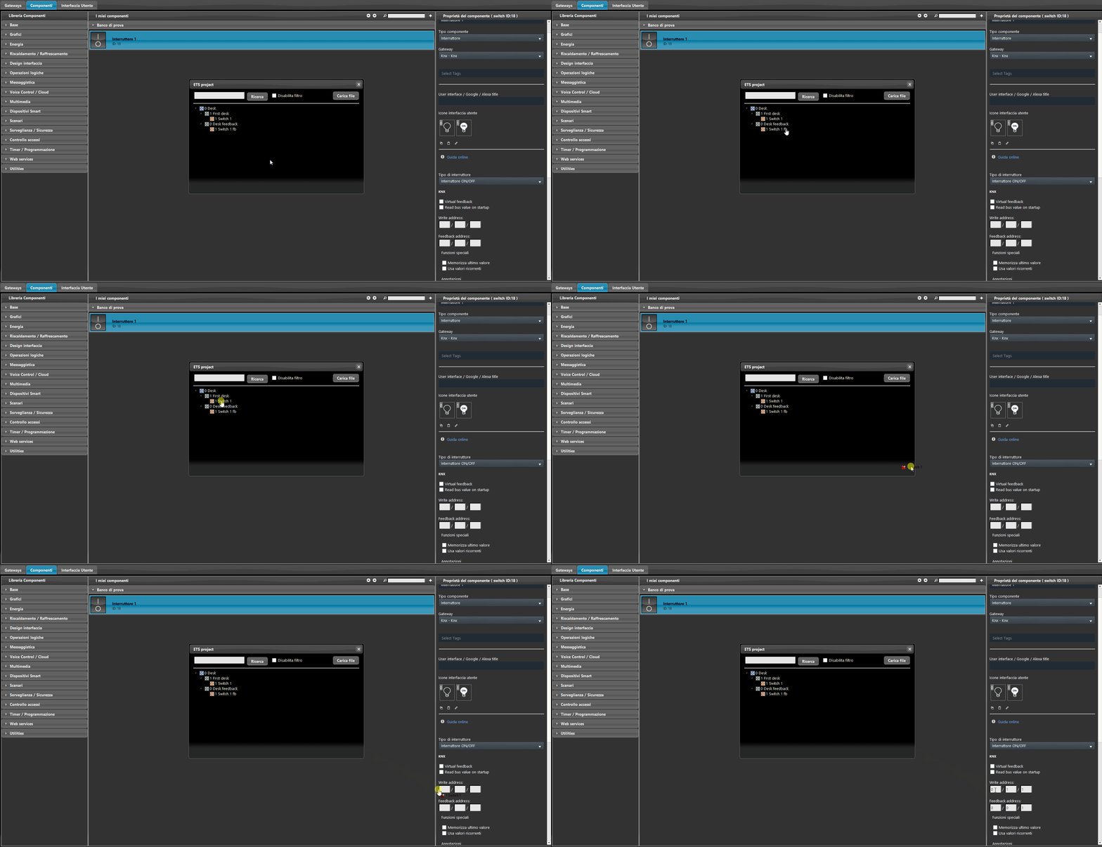
Uploading to the server
Save the project, then select “Project” from the main menu and then “Upload to server”.
A new window will open. Make sure to enter the correct credentials.
Select “OK”: the current project will be uploaded to the server.
See paragraph 1.3 “Uploading to the server” in the chapter “Creating the first project”.
Real-time connection
Select “Project” from the main menu of Ilevia Manager and then “Connect”.
A new window will appear. Make sure to enter the correct credentials.
Finally select “OK”: you will be connected automatically to the server.
Once connected, you can verify in real time whether the component configuration is correct.
See paragraph 1.4 “Real-time connection” in the chapter “Creating the first project”.
Remote connection
From Ilevia Manager:
To connect remotely to an X1, you need to know the public IP or the DDNS assigned to the modem/router to which the Ilevia server is connected.
From Ilevia Control:
To make the connection work, you must open port 18000 to the outside, associated with the IP address of the X1 server, in order to access the system remotely as well.
You can test the service by disconnecting from the local network and accessing your Ilevia Control account over an LTE connection from your mobile device. If port 18000 has been opened correctly, the connection will be established immediately by tapping the account in the app.
Connection to the Auto resolve IP service:
The Ilevia Control app lets you connect to the Ilevia server remotely without setting up two different accounts with two different IP addresses. With the Auto resolve IP option, you can use the same account without entering a public IP address in the settings. To enable it, make sure the “Auto resolve IP” checkbox is selected in the account; remember that, for the option to work, port 18000 must be open. Finally, connect the mobile device to the local network and sign in to the account.
Now, with an LTE connection, it will also be possible to access the account remotely.
Classic user interface
Select the “User interface” section.
Select the “Icons” section and then “Ilevia Icons” in the menu on the right of the screen.
Drag the icons into the boxes in the left area of the screen (Icons and scenes).
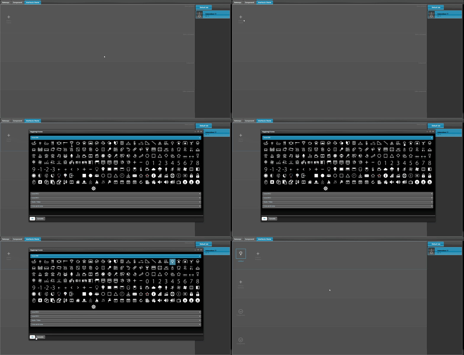
This way, we will set the icons as the main menu (first level) of the user interface.
You can set a secondary menu related to the icon defined at the first level.
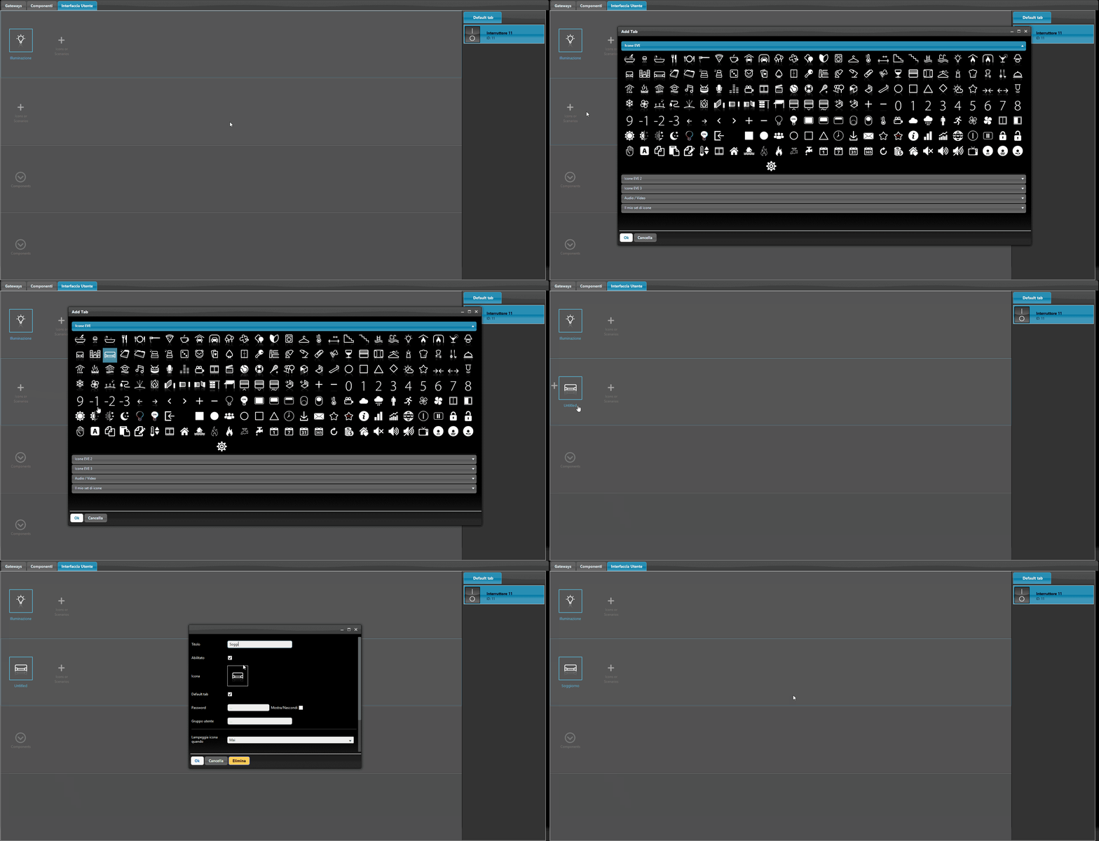
Select the “My components” section, then drag the components into the interface (third and fourth level).
This way you will add the components to the secondary menu created previously.
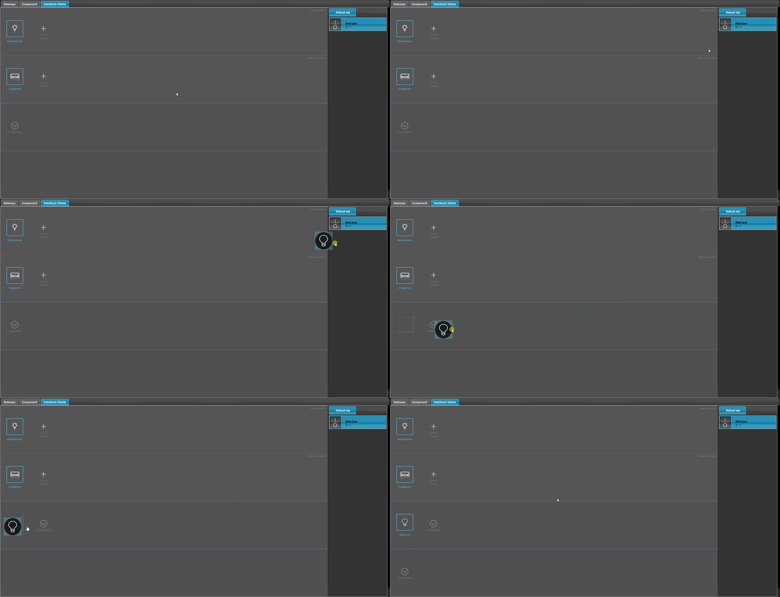
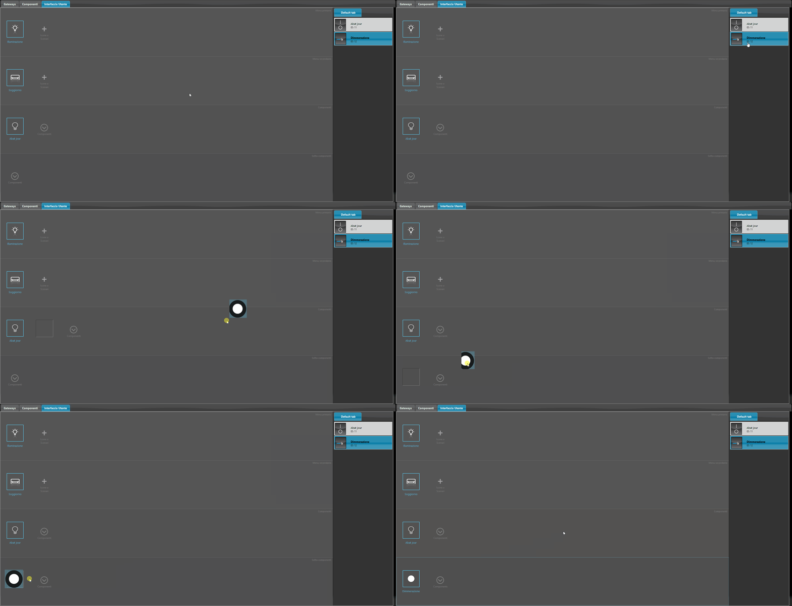
Optional subcomponents can also be added.
Subcomponents are useful with dimmable lights: as you can see in the image below, the component that controls the light intensity is added in the subcomponents row.
Upload to server
Save the project, then select “Project” from the main menu and then “Upload to server”.
A new window will open. Make sure you enter the correct credentials.
Select “OK”: the current project will be uploaded to the server.
See paragraph 1.3 “Upload to server” in the chapter “Creating the first project”.
Accessing Ilevia Control
Launch the Ilevia Control app.
Tap the icon

in the upper-right corner of the app’s main screen.
Choose a title, then enter the Ilevia server IP address and the credentials of the user you want to sign in as.
Once the settings are complete, return to the app’s main page by tapping the icon

in the upper-left corner.
See paragraph 1.7 “Accessing Ilevia Control” in the chapter “Creating the first project”.
Classic user interface operation
The images below show the result of the user interface created in Ilevia Manager.
The first icon you see is the one defined at the first level of the interface, followed by all the others.
Select the main menu icon: you can browse all the other menus and finally interact with the components as configured in the Ilevia Manager project.
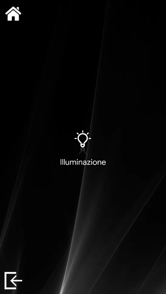
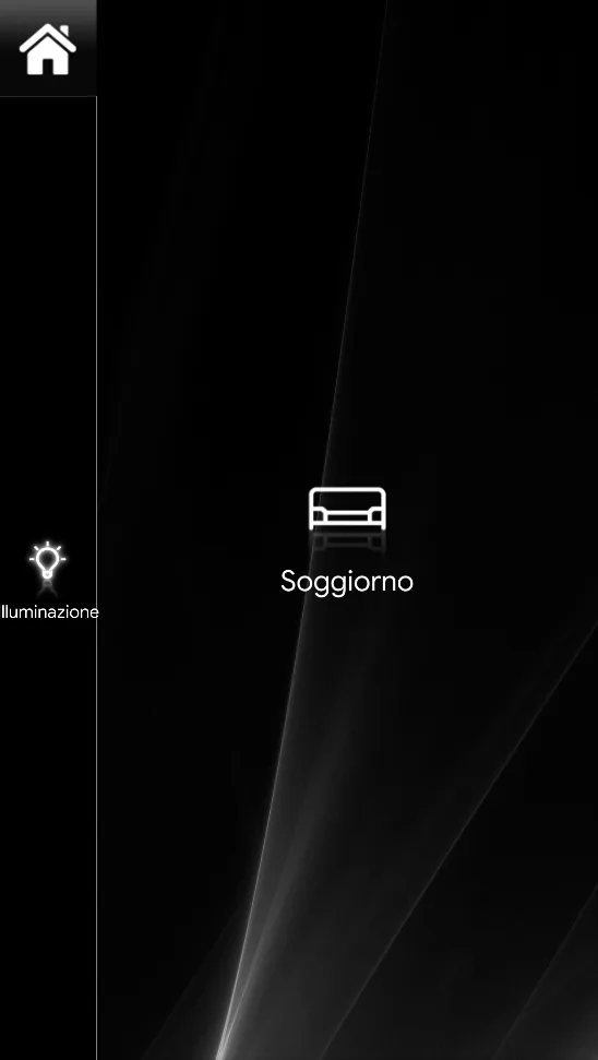
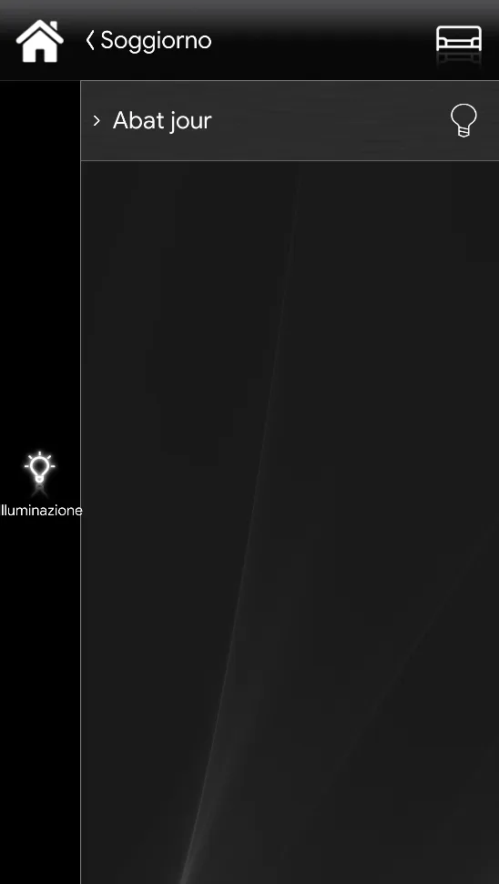
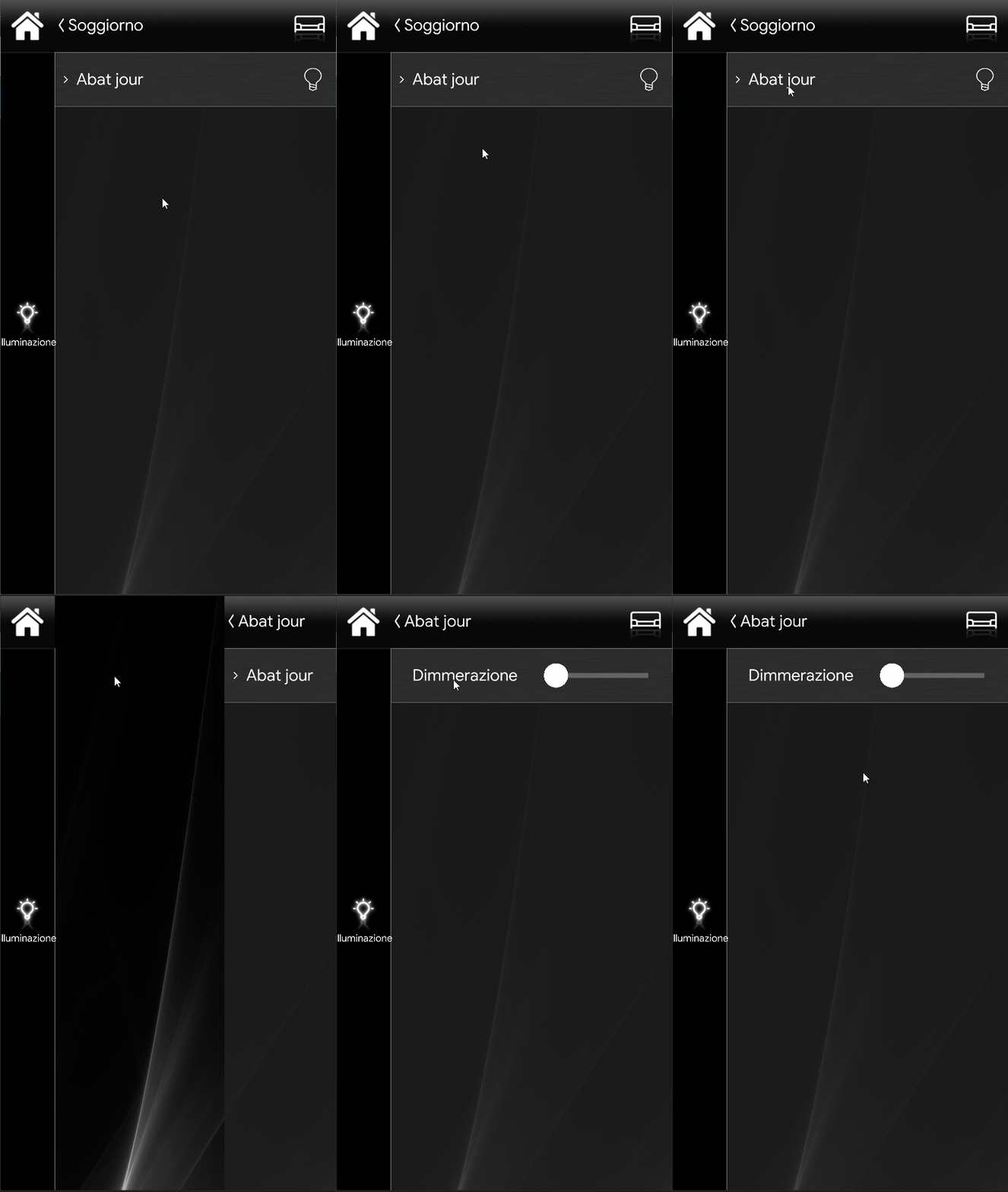
Try turning the light on and off from the app: you will notice the corresponding physical light change state.
Map-based user interface
We will now move on to designing a new user interface with a different style: the two user interface styles have a completely different display. You will need to create a new user in the Ilevia Manager project, because each user has their own interface style.
Creating a new User
Up to now we have been working with a single user (admin) and its interface (current user).
Let’s add a new user to the project: select “Users” in the main menu of Ilevia Manager, then click “New user”.
Clicking “New user” will open the “User management” window.

First of all, you need to know how to add a new user to your project.
You may have noticed the information displayed at the top of the Ilevia Manager window:
Connected user: admin – Current user: admin – Current project: n.d.
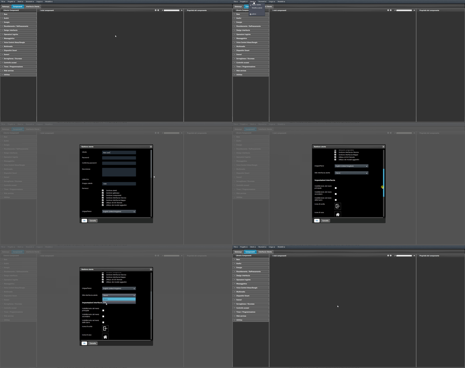
Choose a “Name” and “Password” for the new user and confirm creation.
In this example, we chose the following credentials: Name: Map user – Password: password
You will be asked to choose which interface will be used for the new user.
Once “Interface style: Maps” is selected, additional settings will be shown, allowing you to apply preliminary settings to the user interface properties.
Once the new user has been created, Ilevia Manager will select it automatically:
Connected user: admin – Current user: map user – Current project: n.d.

You can now start creating the new user interface.
Creating the Map Interface
Select the User Interface section. The Map interface consists of two different areas:
1. To add a new menu icon, click the “+” icon to access the Icons panel (right-hand area);
2. Interface area (left-hand area) where the actual interface will be created.
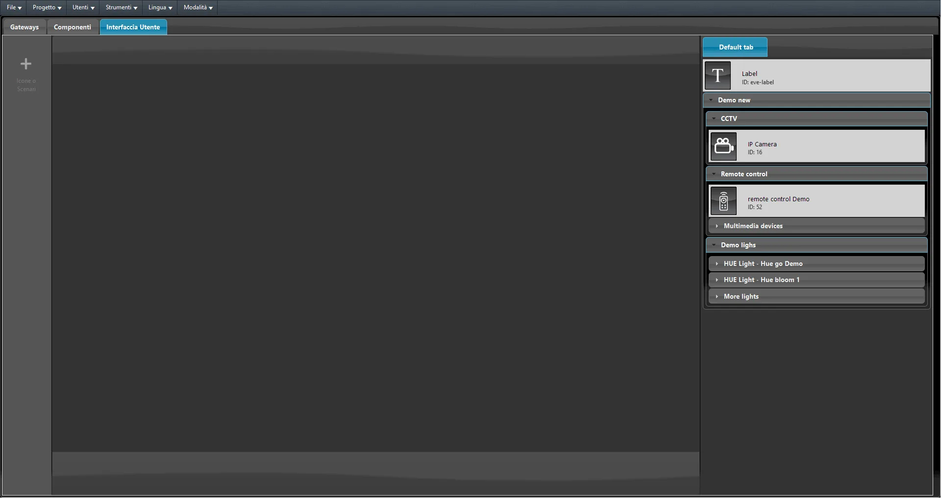
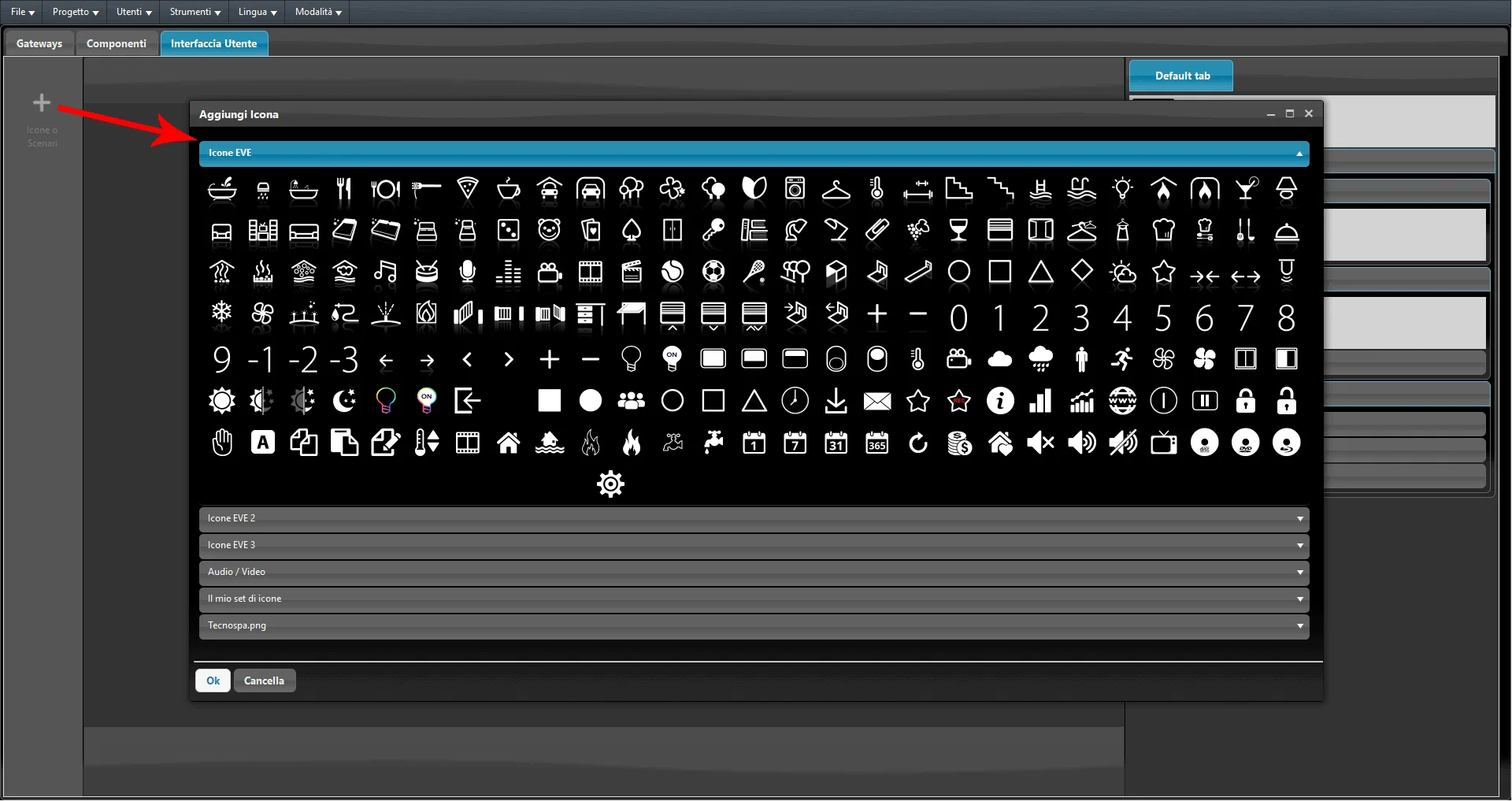
Select the “Icons” section and open the “Ilevia Icons” group on the right side of the screen.
Drag the icons into the left-hand area, where you can add icons or scenarios.
This way, we configure the icon that will be the main menu (main bar) of our user interface.
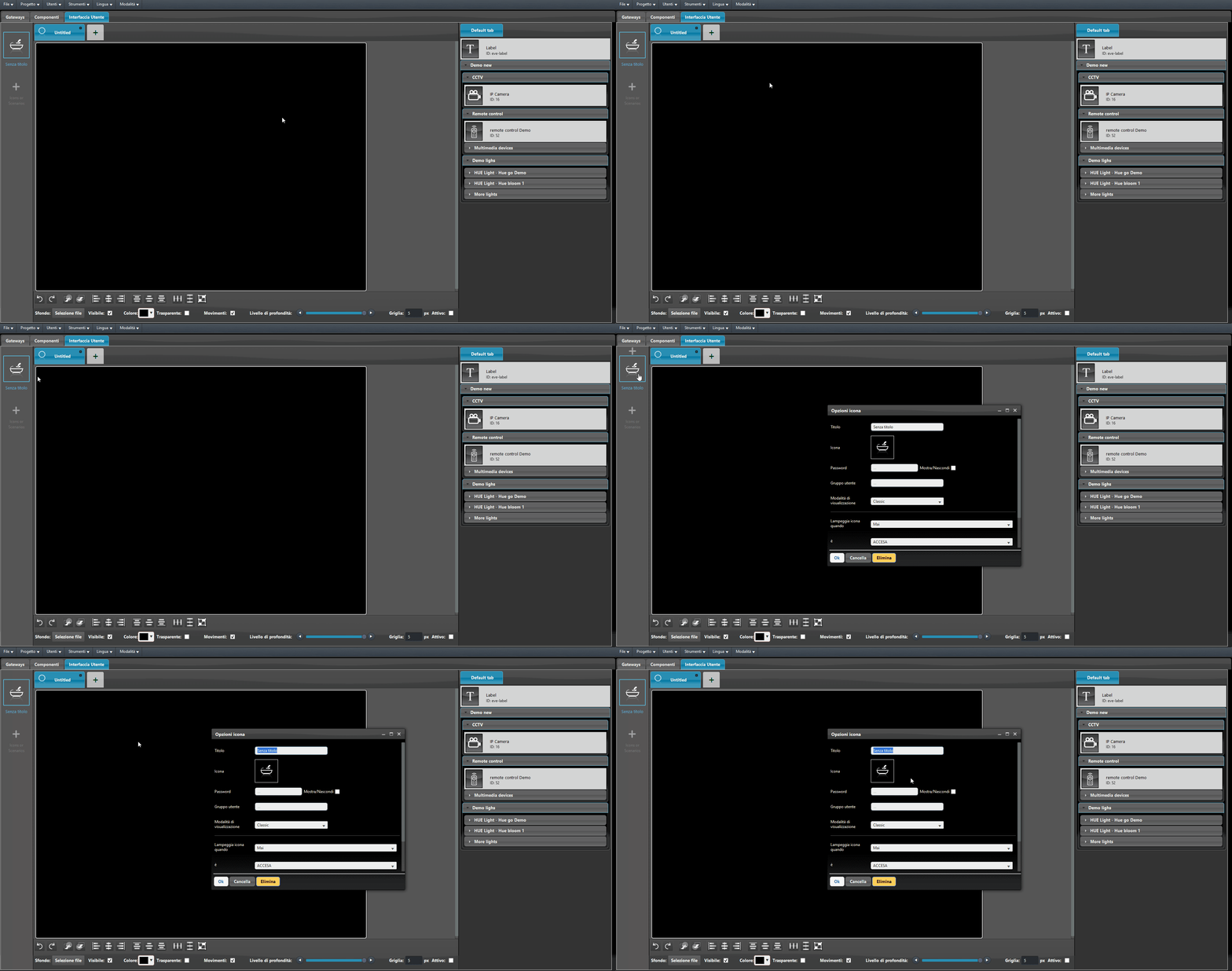
You can edit the icon by double-clicking it with the left mouse button: the icon “Editor” menu will open.
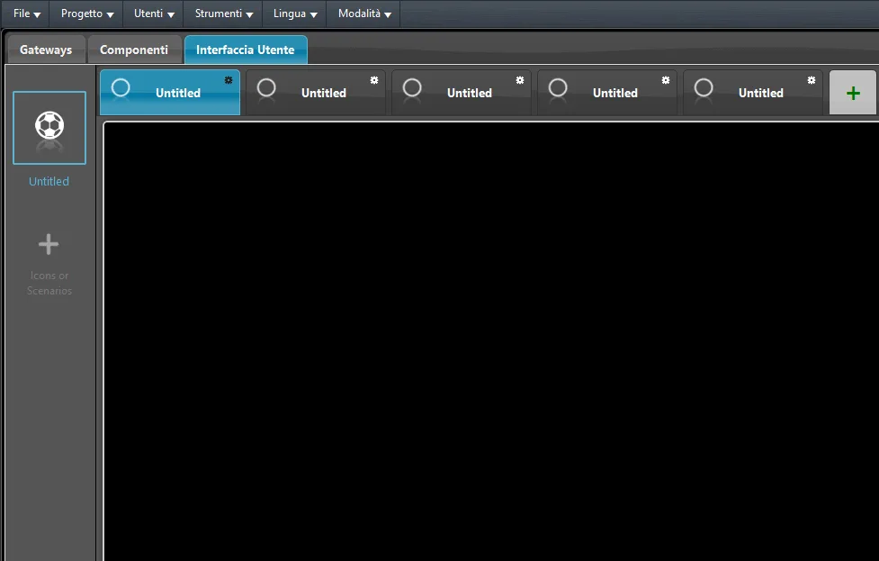
You can now set the secondary menu related to the selected main menu icon.
To create a new submenu, click the icon

immediately after the “Untitled” section at the top of the interface panel.
Each main menu can have an indefinite number of submenus.
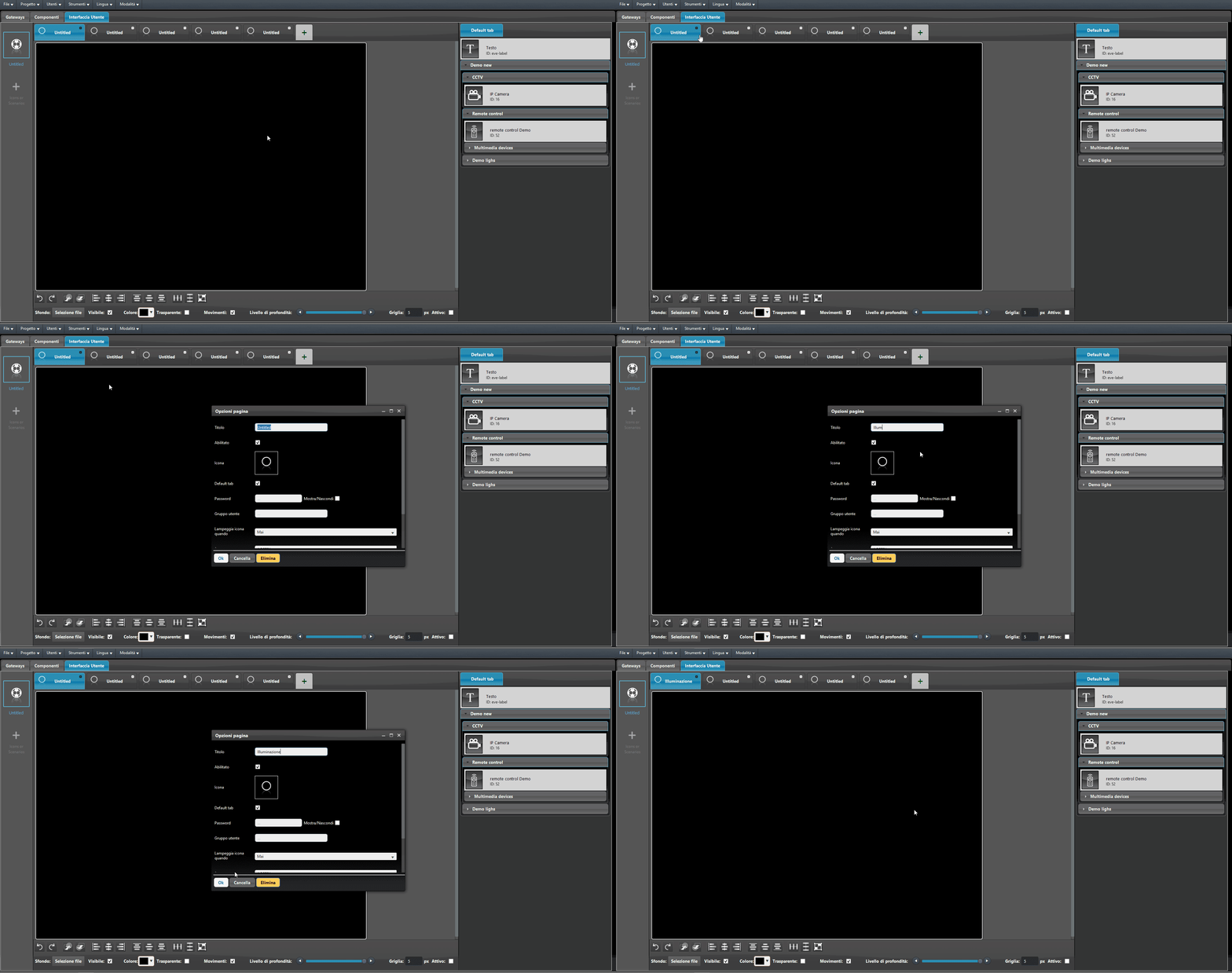
By double-clicking the submenu, you can change its name and icon.
Now we will focus on the interface area where the components to be controlled are placed.
You can modify the interface area using the commands shown below for background settings.
“File selection” lets you choose the background image for the selected submenu.
You can choose whether to make it visible or not and select the background color of the specific submenu.
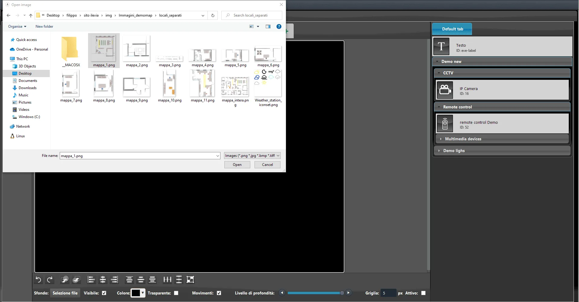
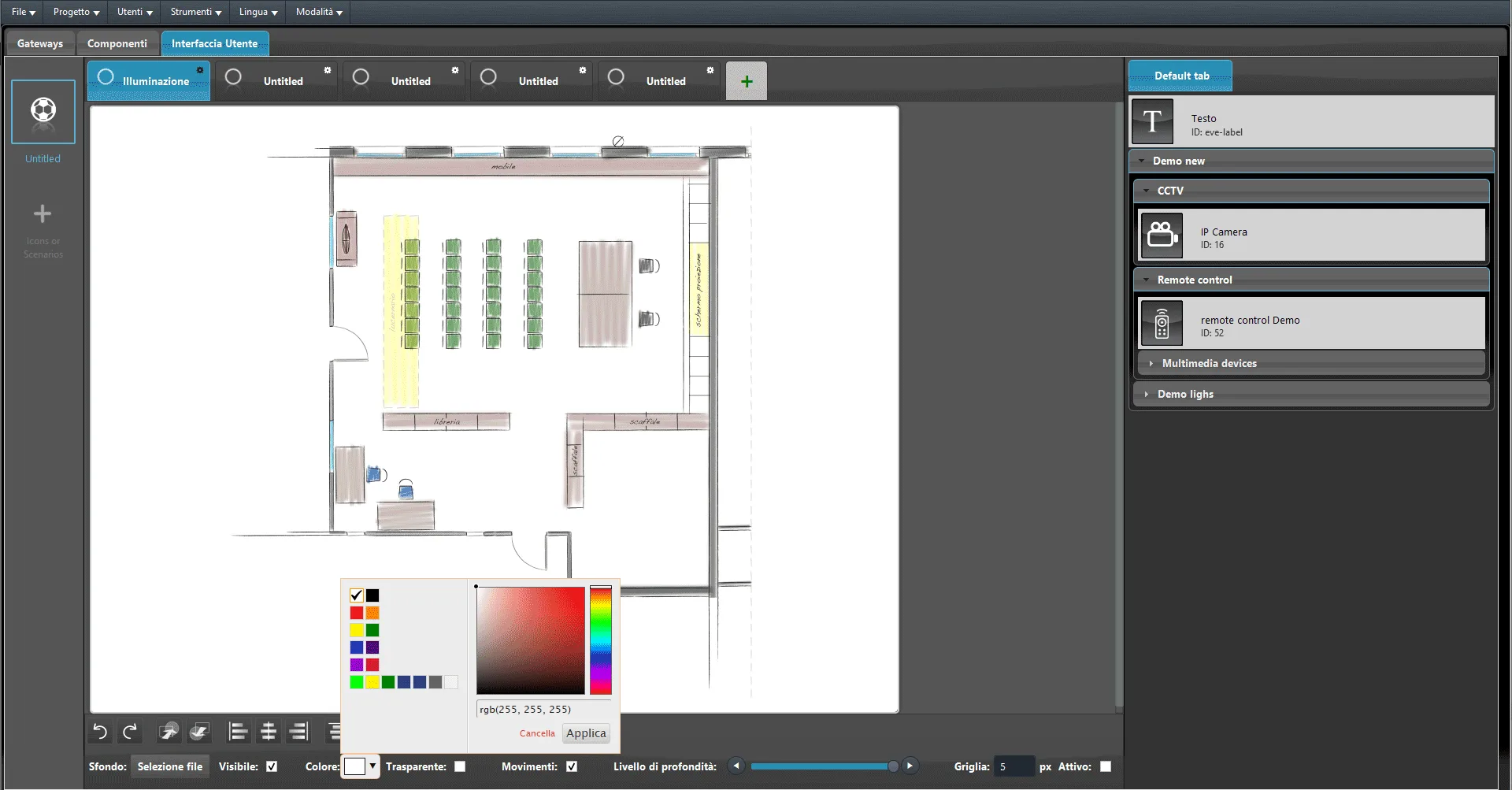
Drag the components you want to add to the user interface into the editor canvas.
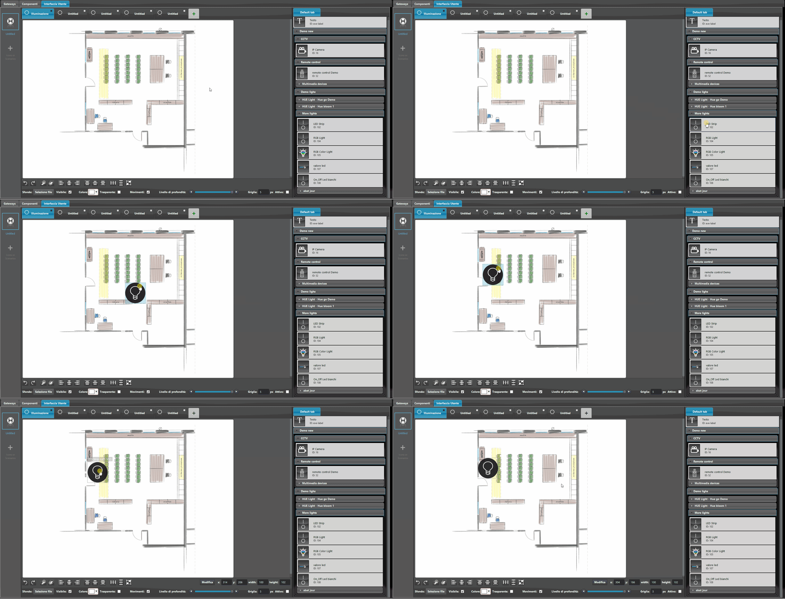
You can now edit these icons: by double-clicking them with the left mouse button, you will enter the icon editor.
Map Interface Operation
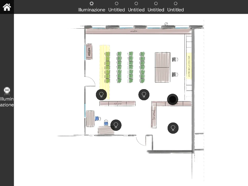
This is the visual result of the interface just created in the Ilevia Manager configuration software.
The first icon displayed will be the one corresponding to the main menu of your interface.
The icons displayed at the top or bottom of the interface correspond to the submenus created.
The central area of the interface editor allows you to create a complete interface with a background image and associated components.
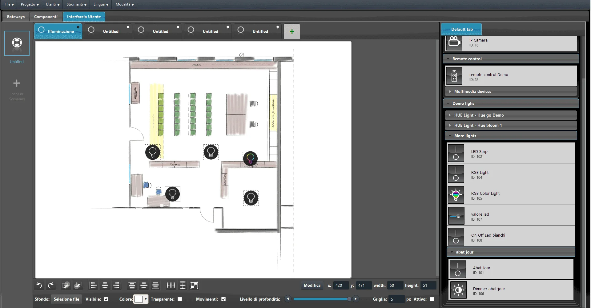
Switch components are represented as empty bulbs when in Off state, which fill up when the light switches to On state.
Try turning the light on and off from the interface: you will notice that the light linked to that component changes state.