Virtual thermostat
How to configure the Virtual thermostat component in Ilevia Manager to control a valve based on setpoint, temperature, and offset.
INTRODUCTION
This component allows you to configure a virtual thermostat logic in the Ilevia system. It becomes very useful when the system does not include temperature control managed by physical thermostats.
USE CASES
The system where the Ilevia server is installed does not include any physical thermostats.
COMPONENT PROPERTIES
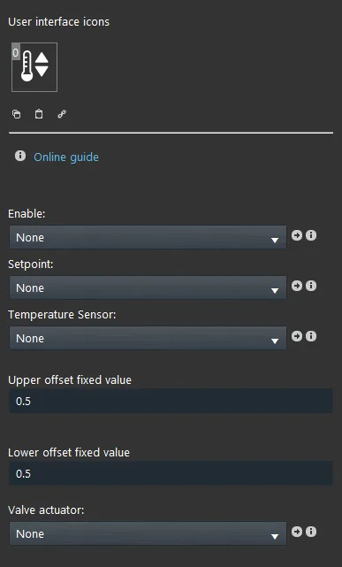
Enable (Optional): By connecting a Switch component, it allows you to enable or disable the entire virtual thermostat logic;
Setpoint: Connect a Setpoint component, which will allow the user to set the temperature;
Temperature sensor: Connect an Info component, used to display the current temperature;
Upper / lower offset value: These two values set the range taken into account between the current temperature and the value set in the Setpoint;
Valve actuator: Connect a Switch component that will be controlled by the logic.
STEP-BY-STEP CONFIGURATION GUIDE
Step 1:
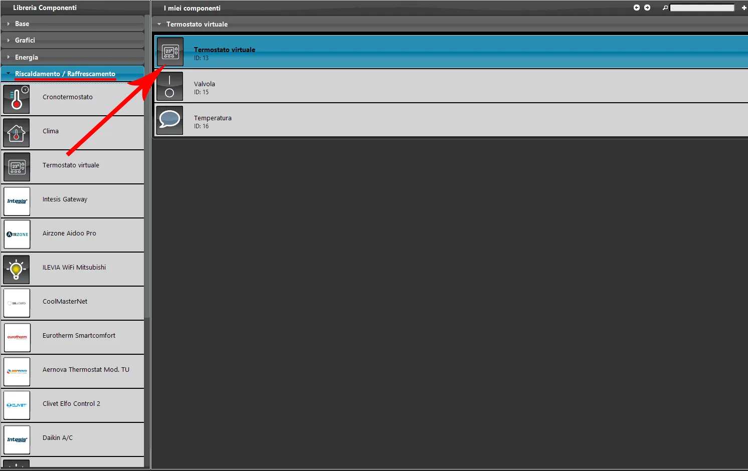
Add the Virtual thermostat component to the project. The component is located in the Heating / Cooling group in the Component library section.
Step 2:
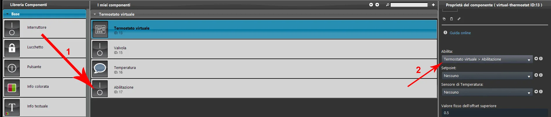
1. Add a Switch component. 2. Connect it as the enable component for the entire Virtual thermostat.
Step 3:
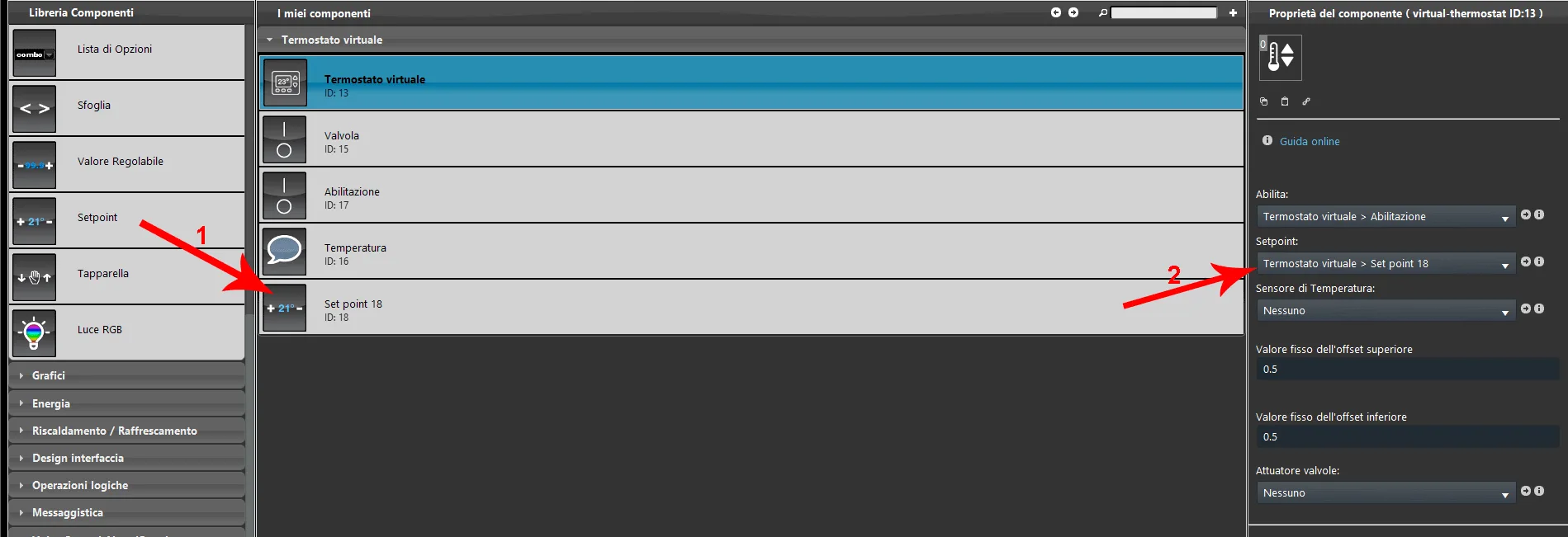
1. Add a new Setpoint component and make sure its gateway is EVE-GHOST. 2. Connect it to the option list called Setpoint.
Step 4:
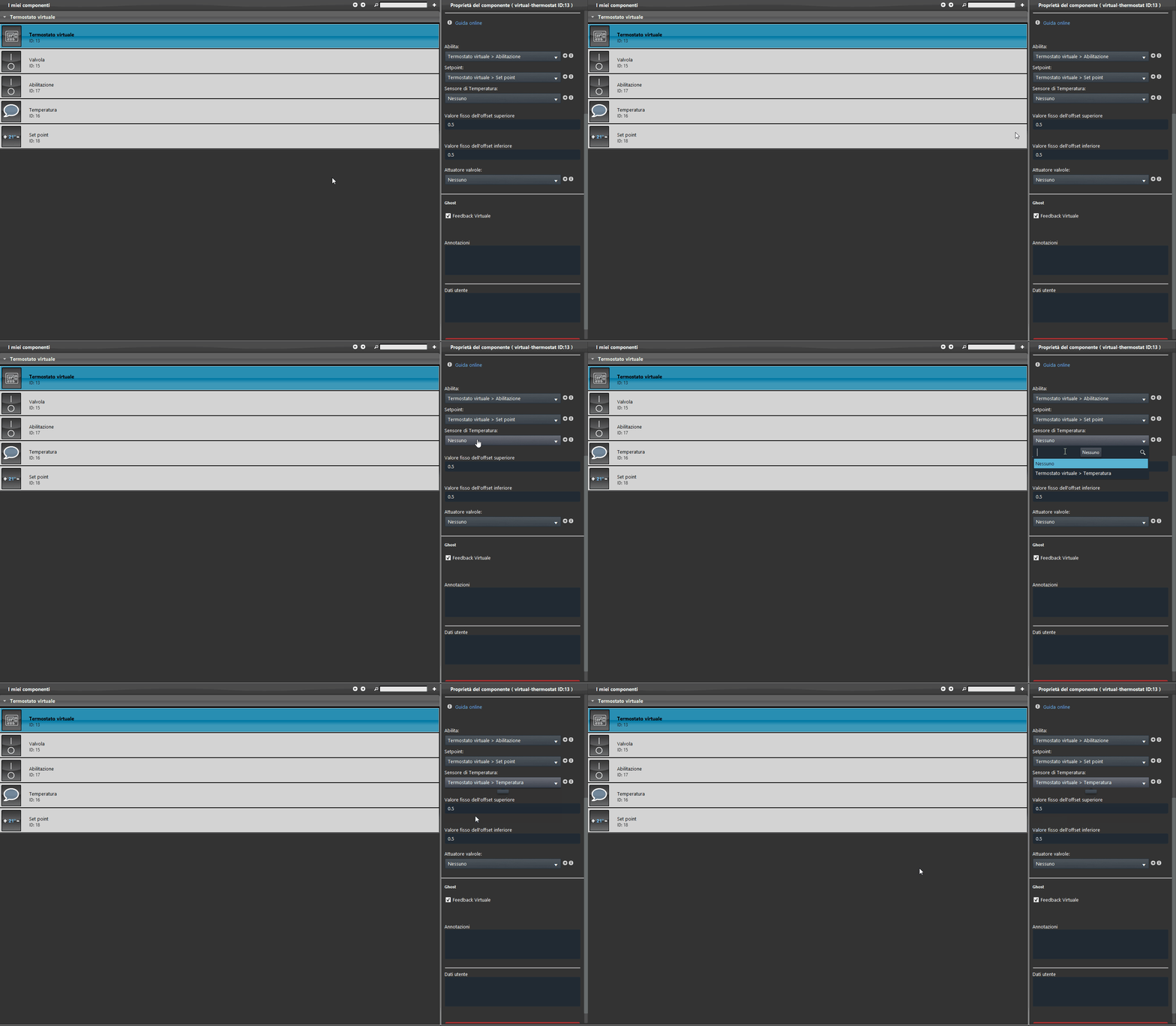
Add an Info component that will be used to display the temperature value, and assign it to the option list called Temperature sensor.
Step 5:
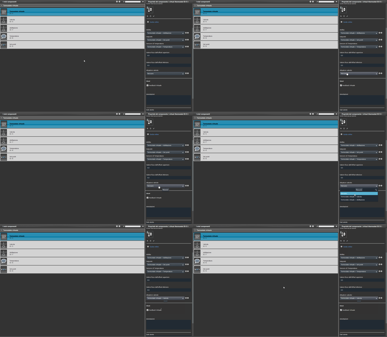
Finally, configure the Switch component so that it opens or closes the valve, then assign it to the parameter called Valve actuator.
Step 6:
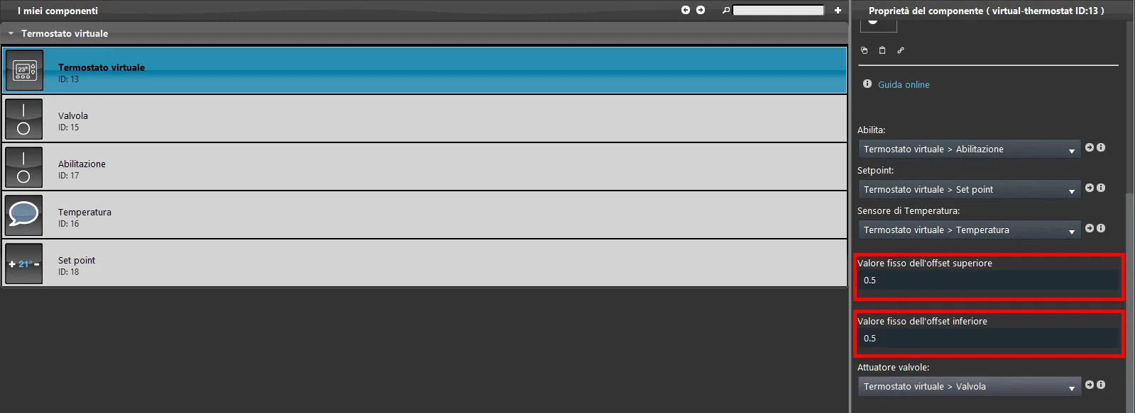
Customize the upper and lower offset values according to your needs. They define the hysteresis value, that is, the two values at which the valve is activated.
Classic interface
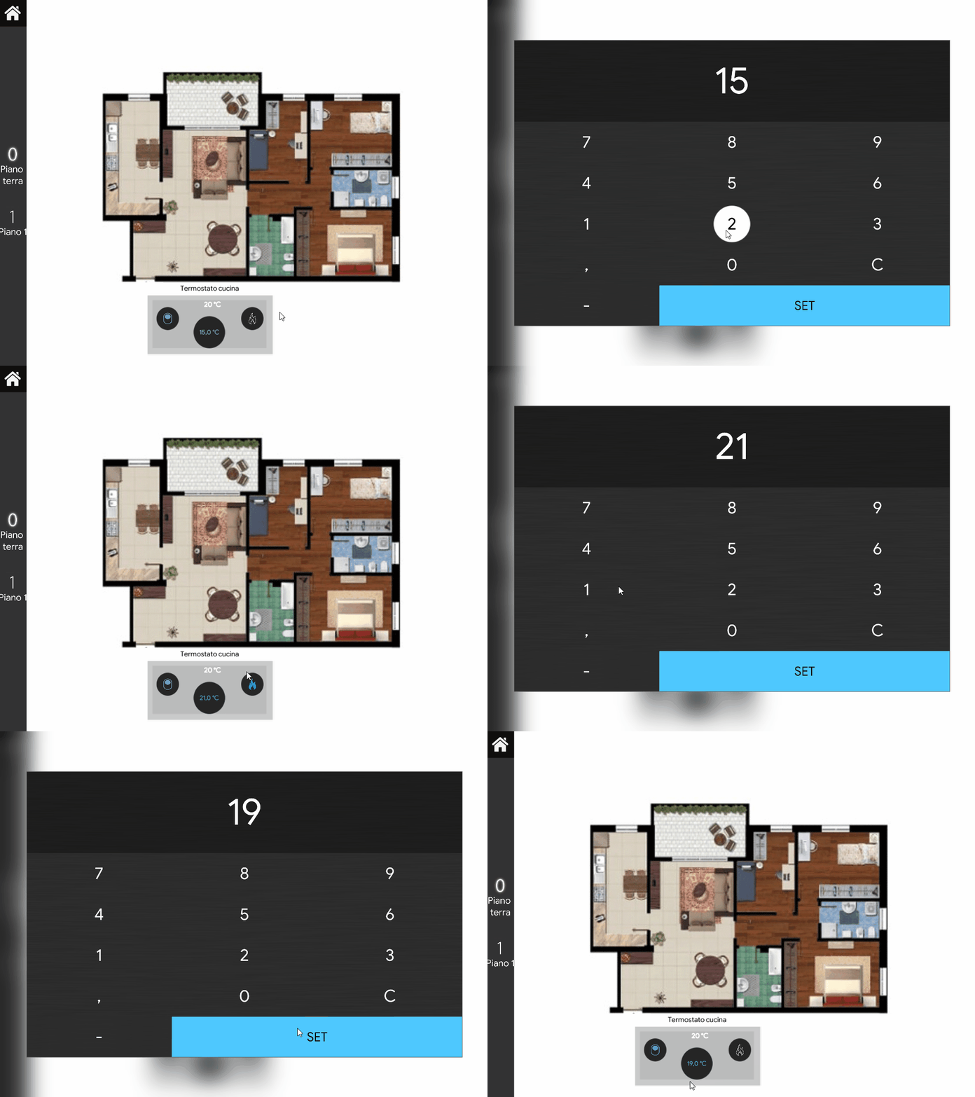
This is one of the possible views of the Virtual thermostat component in the classic user interface.
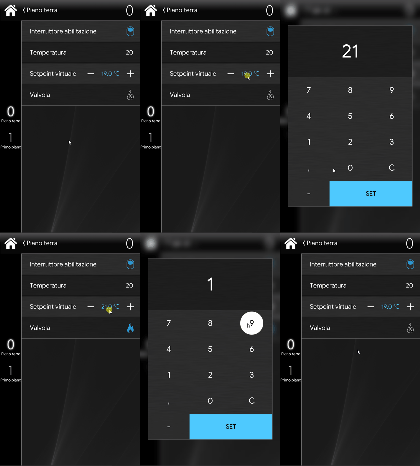
Map interface
This is one of the possible views of the Virtual thermostat component in the Map user interface.