
Demo project: Load control
This guide explains how a typical configuration of a Load control module is structured using a downloadable demo project.
Introduction
The example below is a demo project for a complete configuration of the Load control module. Since it is a demo, you can use it as a configuration reference or add it to your own project.
Configuration components
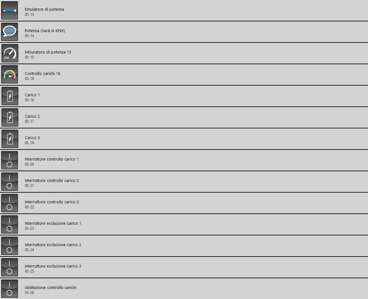
Power emulator: This adjustable value simulates the currently consumed active power;
Power (configured with KNX): This Info component, in our case, represents the value of the power emulator; in your case, it will be a KNX energy meter;
Power meter: This component is part of the Load control component configuration; when inserted in the user interface, it allows the values of the Info components entered in its settings to be displayed. Click here to view the guide.
Load control: This is the component that manages the entire load disconnection and restoration procedure based on a threshold set within it. Click here to view the configuration guide;
Load 1, 2, 3: These Load components are made up of 2 Switch components. These loads are disconnected when the power threshold is reached and restored when the consumed power drops below the threshold value;
Load control switch 1, 2, 3: These three Switch components must be connected directly to the physical load device and allow actuation via Ilevia X1;
Load exclusion switch 1, 2, 3: For these three Switch components, if the state is On the load is set to manual mode, if the state is Off the Load component is set to automatic mode. (Manual = the Load component is not controlled by the Load control component; Automatic = the load is controlled by the Load control component);
Enable load control: This component Switch enables or disables the Load control component.
Click the link below to download the demo project for the Load control module configuration.